Key supporting structure

a supporting structure and key technology, applied in the direction of tactile feedback, contact mechanisms, electrical appliances, etc., can solve the problems of reducing the material thickness of the scissor-type component, the keycap is tilted, and the situation of false key triggering, etc., and achieves poor structural strength

Active Publication Date: 2017-07-06
LITE ON ELECTRONICS (GUANGZHOU) LTD +1
View PDF4 Cites 7 Cited by
  • Summary
  • Abstract
  • Description
  • Claims
  • Application Information

AI Technical Summary

Benefits of technology

[0006]A primary object of the present disclosure is to provide a key supporting structure adopting a composite structure, which can overcome the disadvantages of poor structural strength and failure to be thinned of a conventional scissor-type component made of a plastic and also can solve the problems of a scissor-type structure made of a metal material.
[0011]The advantageous effect of the present disclosure is that the scissor-type structure preserves good strength and hardness with a reduced thickness and size, and is not easily bendable, thus meeting the requirements of thinned keyboards. Also, the scissor-type component preserves the properties of a plastic material, resulting in reduced collision noise, reduced friction, and wear resistance in operation.

Problems solved by technology

However, with the current trend of thin keyboards, the material thickness of the scissor-type component is reduced, and the use of the POM material in the fabrication of the scissor-type component will face the problem of insufficient structural strength, resulting in easy bending of the scissor-type component when the keycap is pressed, thus causing the tilting of the keycap and the situation of false key triggering.
In view of the above reasons, the conventional scissor-type component made of the POM resin material cannot meet the requirements of thin keyboards.

Method used


Image

  • Key supporting structure
  • Key supporting structure
  • Key supporting structure

Examples


Embodiment Construction

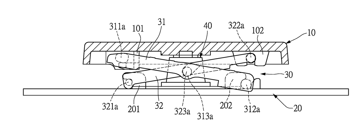
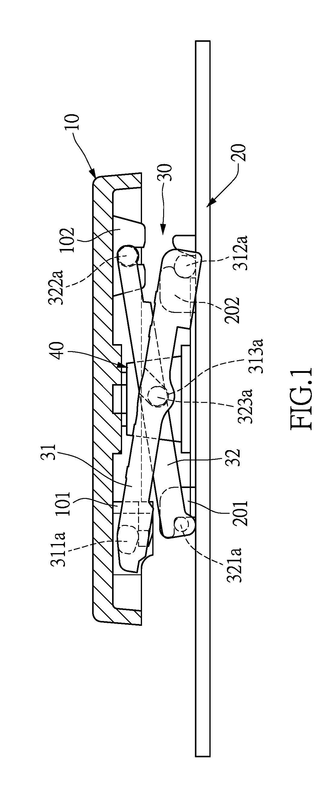
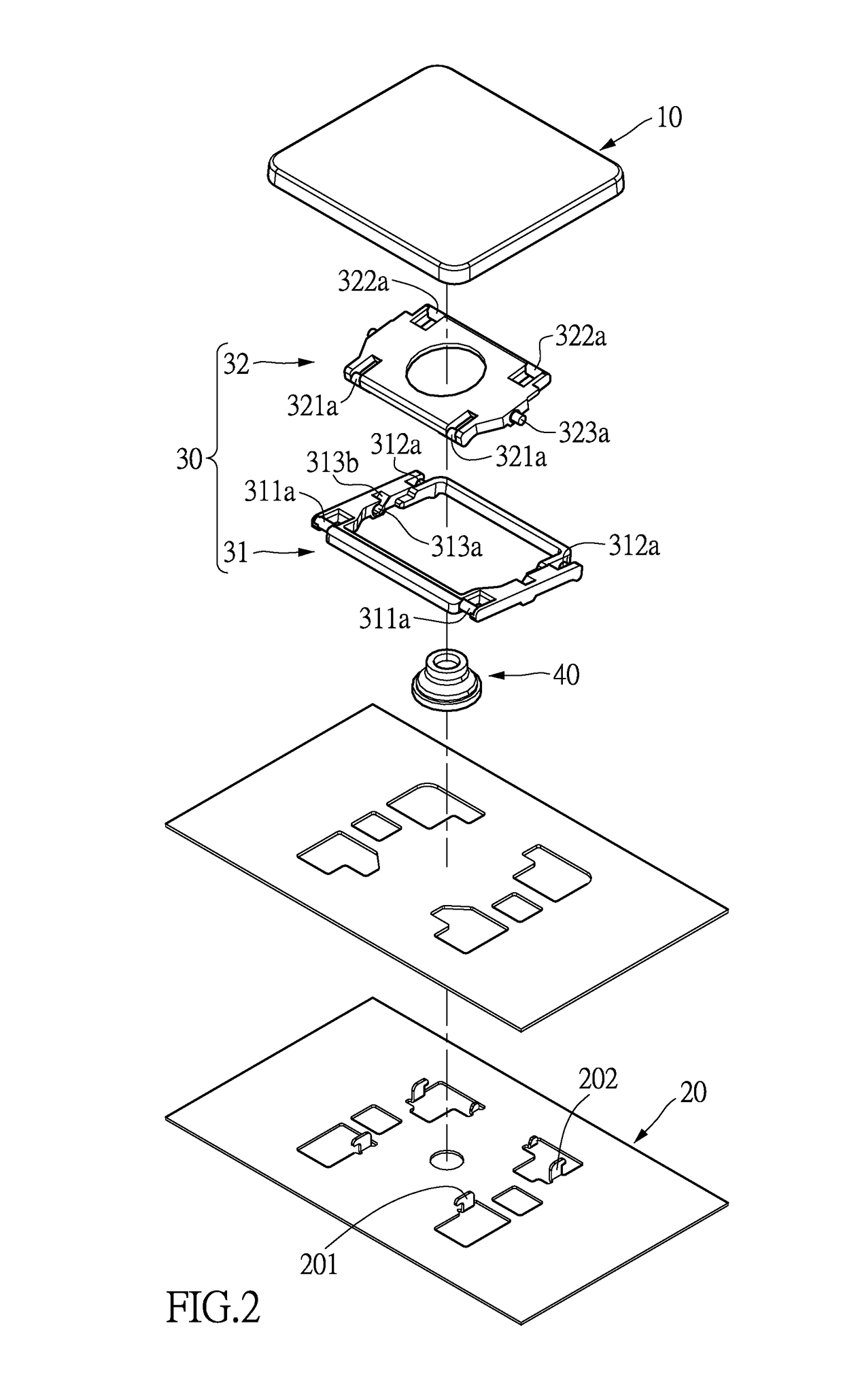
[0020]The present disclosure provides a key supporting structure. As shown in FIG. 1 and FIG. 2, the key supporting structure comprises a scissor-type component 30, and the scissor-type component 30 is connected between a base 20 of a keyboard and a keycap 10, for positioning the keycap 10 in such a manner that it can move upward and downward along a path perpendicular to a top surface of the base 20. A resilient dome 40 is also disposed between the keycap 10 and the base 20. The resilient dome 40 will contact with a conductive thin film (not shown) of the keyboard module when the keycap 10 is pressed downward to a certain depth, to generate a pressing signal.

[0021]Two sides of a bottom surface of the keycap 10 are provided with a first limiting portion 101 and a second limiting portion 102 respectively. The top surface of the base 20 is provided with a third limiting portion 201 and a fourth limiting portion 202 respectively at positions corresponding to the first limiting portion ...


PUM


Abstract

Disclosed is a key supporting structure. The key supporting structure includes a scissor-type component having a first supporting element and a second supporting element that are pivotally connected to each other. The first supporting element has a first frame, and two end of the first frame have at least one first pivot and at least one second pivot respectively. The second supporting element has a second frame, and two end of the second frame have at least one third pivot and at least one fourth pivot respectively. The first frame and the second frame are made from a powder sintered material. The first pivot, the second pivot, the third pivot, and the fourth pivot are formed on the first frame and the second frame by plastic injection molding method.

Description

TECHNICAL FIELD[0001]The present disclosure relates to a key supporting structure, and more particularly to a key supporting structure adapted for thin keyboards.BACKGROUND ART[0002]With the increasing popularity of ultra-thin notebook computers and tablet computers, keyboards for these thin notebook computers and tablet computers also are continually evolving toward thinness.[0003]In the structure of a thin keyboard, a scissor-type supporting mechanism (also referred to as a scissor) mostly is used as a supporting and positioning structure of a keycap of the keyboard. The keyboard structure using the scissor-type supporting mechanism generally comprises a base, a keycap, a scissor-type component, a resilient dome, and a conductive film The scissor-type component is connected between the keycap and the base, for positioning the keycap above the base in a movable upward and downward manner[0004]A conventional scissor-type component mostly is manufactured from a POM resin material by ...

Claims


Application Information

Patent Timeline
Patent Type & Authority Applications(United States)
IPC IPC(8): F16M13/02H01H13/70
CPCF16M13/02F16M2200/061H01H13/70H01H3/125H01H13/705H01H2229/044H01H13/7065H01H2215/006G06F3/02
Inventor YEN, MING-FUWU, CHIA-SHIUN
Owner LITE ON ELECTRONICS (GUANGZHOU) LTD
Why Eureka
Try Eureka