Tunable daylight experience using micro faceted foils

Active Publication Date: 2017-07-06
SIGNIFY HLDG BV
View PDF1 Cites 10 Cited by
  • Summary
  • Abstract
  • Description
  • Claims
  • Application Information

AI Technical Summary

Benefits of technology

[0040]Especially, the optical elements have one or more of a refractive functionality and total internal reflection functionality to the light source light. Of course, both types of functionalities may be available. Further, as indicated above, elements may have both functionalities. For

Problems solved by technology

One of the main issues with presently known solutions is their low optical efficiency, which can easily be below 50%.
Other disadvantage of some prior art solutions is that the intensity of the ‘blue sky’ and the white downward light cannot be independently controlled.
Yet another problem of prior art solutions is the relative large system of the essential optic

Method used


Image

  • Tunable daylight experience using micro faceted foils
  • Tunable daylight experience using micro faceted foils
  • Tunable daylight experience using micro faceted foils

Examples


Embodiment Construction

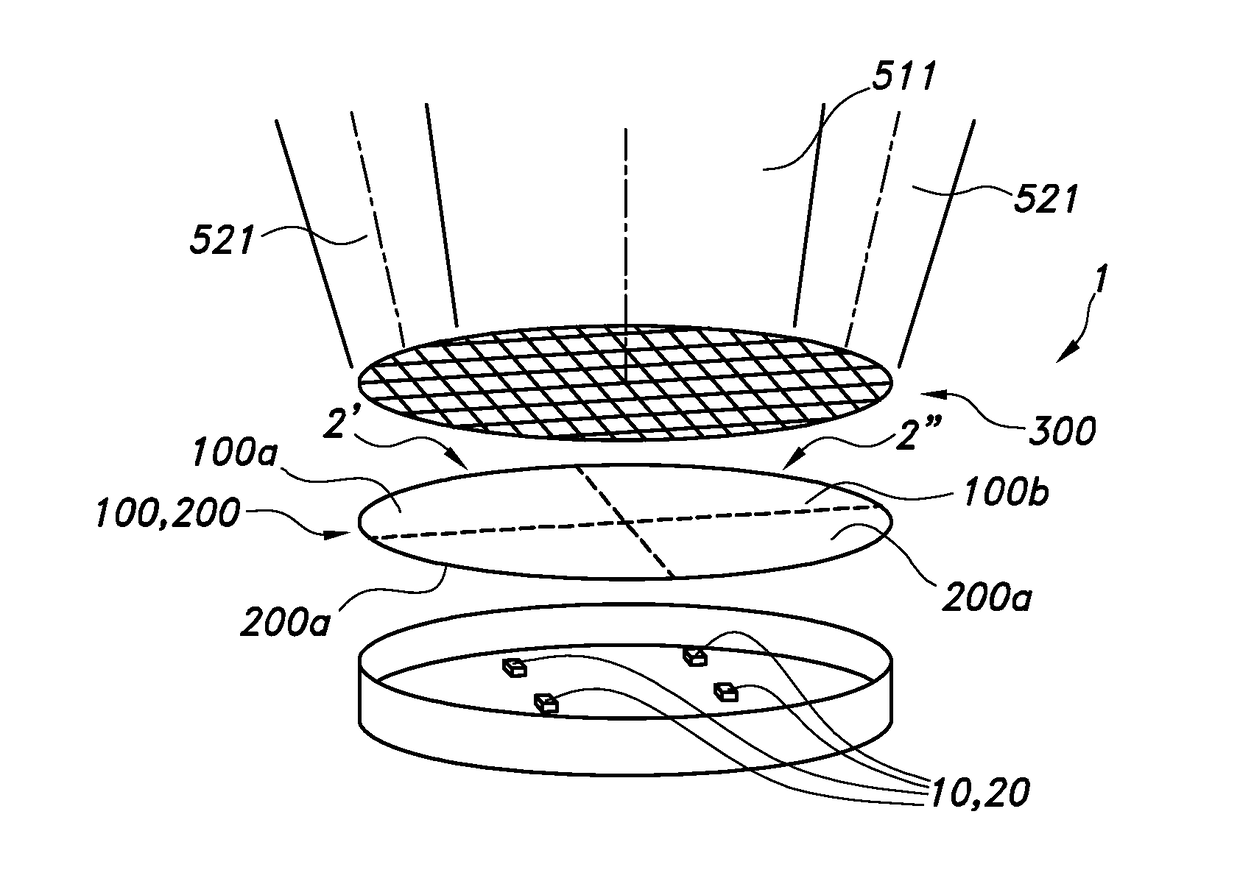
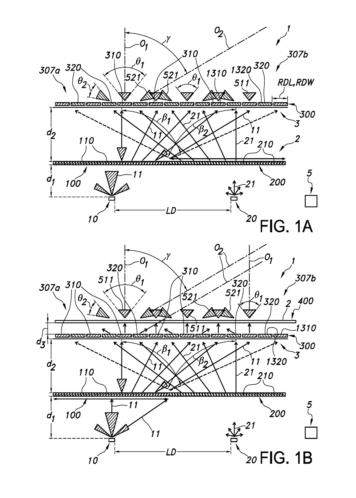
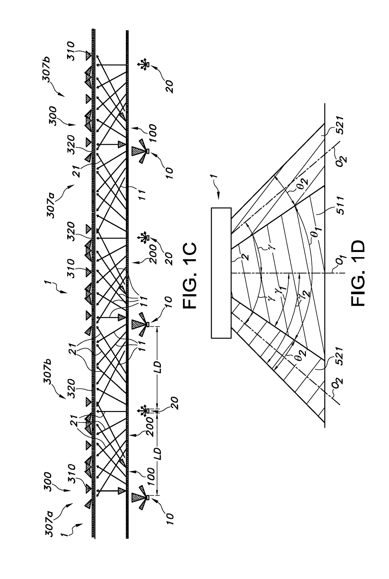
[0070]A first embodiment may comprise two micro facetted foils as depicted FIG. 1A. In this embodiment we use two different colored LEDs (e.g. white and blue). This figures show a lighting unit 1 comprising a first light source 10 and a second light source 20 configured to provide light source light 11,21 having different spectral distributions. Further, the lighting unit 1 comprises a light transmissive first light redistribution window 100 configured downstream of the first light source 10 and a light transmissive second light redistribution window 200 configured downstream of the second light source 20. Further, the lighting unit 1 comprises a light transmissive redirection window 300 configured downstream of the first light redistribution window 100 and the second light redistribution window 200, and optionally a diffuser window 400 configured downstream of the light transmissive redirection window 400, as schematically depicted in FIG. 1B. The redirection window 300, or the opt...


PUM


Abstract

The invention provides a lighting unit (1) for providing daylight experience for a human. The lighting unit (1) comprises: a first light source (10) and a second light source (20) configured to provide light source light (11,21) having different spectral distributions, a light transmissive first light redistribution window (100) configured downstream of the first light source (10) and a light transmissive second light redistribution window (200) configured downstream of the second light source (20), a light transmissive redirection window (300) configured downstream of the first light redistribution window (100) and the second light redistribution window (200), and optionally a diffuser window (400) configured downstream of the light transmissive redirection window (400).

Description

FIELD OF THE INVENTION[0001]The invention relates to a lighting unit comprising a plurality of light sources and a light transmissive window. The invention further relates to such lighting unit for use to provide daylight perception.BACKGROUND OF THE INVENTION[0002]The use of lighting units to simulate daylight or skylight is known in the art. WO2013011410, for instance, describes a lighting element used for obtaining a skylight appearance, which comprises a white light emitting means for emitting white light, a blue light emitting means for emitting blue light and a Fresnel lens. The Fresnel lens is arranged to receive light from the white light emitting means and from the blue light emitting means. The white light emitting means is arranged in a first relative position with respect to the Fresnel lens to collimate at least a part of the light emitted by the white light emitting means to obtain a collimated directed light beam in a specific direction. The blue light emitting means ...

Claims


Application Information

Patent Timeline
IPC IPC(8): F21V9/02F21V5/00F21V7/00F21V3/00F21V5/04
CPCF21V9/02F21V3/00F21Y2115/10F21V7/0091F21V5/002F21V5/045F21V5/008F21Y2105/10
Inventor GOMMANS, HENDRIKUS HUBERTUS PETRUSVAN GHELUWE, JOCHEN RENAAT
Owner SIGNIFY HLDG BV
Why Eureka
Try Eureka