Dynamic heating system

a heating system and dynamic technology, applied in the direction of coupling device connection, heating type, sustainable building, etc., can solve problems such as static solutions, and achieve the effect of increasing or decreasing the heat generation of said elements

Inactive Publication Date: 2017-07-06
EXPLODED VIEW SL
View PDF2 Cites 2 Cited by
  • Summary
  • Abstract
  • Description
  • Claims
  • Application Information

AI Technical Summary

Benefits of technology

[0008]Moreover, the installation assembly is very simple, since it only requires placing the network connection on the basic floor structure where it is to be applied and, thereafter, placing the covering tiles over said network connection, the position of the tiles being determined by the structure of the network connection, by making a connection core of each tile coincide with the network connection node connectors.
[0009]On the other hand, the programmable controller, combined with an individual relationship with

Problems solved by technology

However, at the heating system application sites, there is usually a need to apply a different heat supply to the different spaces covered by the same heating system, which in present-day installations is generally solved by pre-determining the installation as a function of

Method used


Image

  • Dynamic heating system
  • Dynamic heating system

Examples


Embodiment Construction

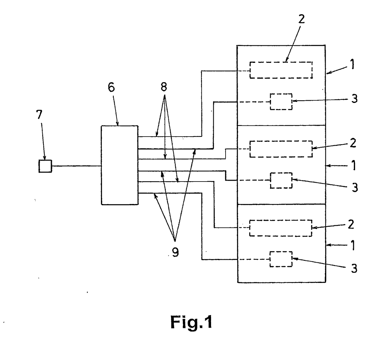
[0013]The object of the invention relates to a heating system in the form of a modular radiant surface, with a dynamic functional embodiment that allows for the individual supply of the necessary heat to each surface point of the heating system application space.

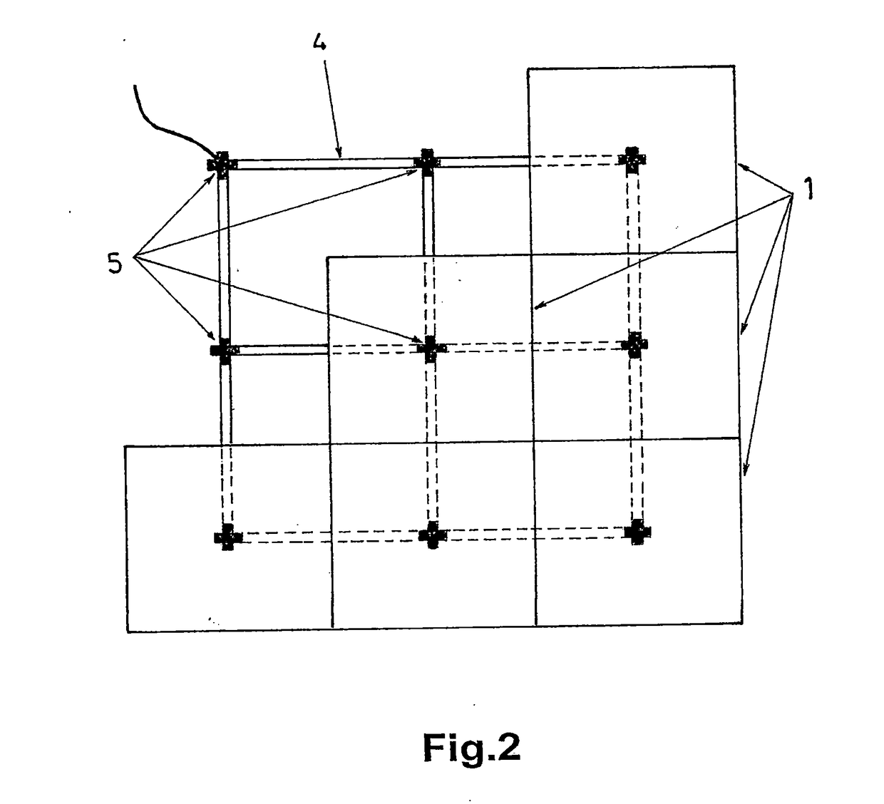
[0014]The proposed heating system comprises a covering that is formed, for example, by floor tiles (1), the interior of each incorporating at least one electrical heat resistance (2) and one thermal temperature-measuring sensor (3).

[0015]Below the covering, there is a scalable network connection (4) defined by partial modular sets which are associated, in the form of a grid, with a distribution corresponding to the grid nodes at points that coincide with a connection point of each of the tiles (1) of the covering, according to the arrangement thereof in the application assembly. In order to facilitate the positioning of the tiles (1) in the application assembly, the connection point thereof with respect to the network connec...


PUM


Abstract

The invention relates to a dynamic heating system in the form of a radiant surface, comprising a covering formed by tiles (1), each tile (1) containing at least one electrical heating resistance (2) and a thermal temperature-measuring sensor (3), a connection network (4) being arranged below the covering in the form of a grid, the tiles (1) being connected to the nodes of said grid electrically and via data transmission, while said connection network (4) is connected to a programmable controller (6) which establishes an individual electric power supply to each of the tiles (1) according to the temperature.

Description

FIELD OF THE INVENTION[0001]The present invention relates to the thermal conditioning of premises, and proposes a dynamic heating system in the form of a radiant surface, which has a modular structuring the characteristics whereof make the system very advantageous to fulfil its function.PRIOR ART[0002]There are various heating systems for the thermal conditioning of premises, such as electric or combustion furnaces, hot water radiators, air circulation, radiant floors, etc.[0003]Said systems are selected for each application on the basis of factors such as the installation cost, the required heat output, the energy consumption, etc., and there are solutions that make it possible to control, whether manually or automatically, by means of thermostats, the turning on and off of the heating system or the passage of the heat flux, in order to maintain a given temperature at the application sites.[0004]However, at the heating system application sites, there is usually a need to apply a di...

Claims


Application Information

Patent Timeline
IPC IPC(8): F24D13/02H01R13/502E01C11/26
CPCE01C11/265F24D13/024F24D13/02H01R13/502E01C11/26H05B1/0277H05B3/283H05B2203/007H05B2203/016H05B2203/026Y02B30/00
Inventor MARTI FIBLA, GURGO, LLUCMARTIN SERRANO, LARA
Owner EXPLODED VIEW SL
Why Eureka
Try Eureka