Electrical Connector and Method of Making It

a technology of electrical connectors and connectors, applied in the direction of coupling contact members, fixed connections, coupling device connections, etc., can solve the problems of sensitivity to shock and vibration typically increasing, and the unsatisfactory, and achieve the effect of low manufacturing cost, low volume and low cos

Inactive Publication Date: 2017-07-06
FAN CHIH PENG +4
View PDF13 Cites 27 Cited by
  • Summary
  • Abstract
  • Description
  • Claims
  • Application Information

AI Technical Summary

Benefits of technology

[0023]It is a further objective of this invention to provide an electrical connector which can be permanently or semi-permanently assembled to a mating circuit element in a simple fashion which is compatible with high volume, low cost manufacturing.
[0024]It is a further objective of this invention to provide an electrical connector which can be permanently or semi-permanently assembled to a mating circuit element without requiring complex and costly tooling.
[0025]It is a further objective of this invention to provide an electrical connector which can be permanently or semi-permanently assembled to a mating circuit element such as an FPC or a PCB and which can be assembled and interconnected to that circuit element without requiring any additional hardware or tooling to retain the connector in its compressed and actuated state.
[0026]It is a further objective of this invention to provide an electrical connector which can be permanently or semi-permanently assembled to ...

Problems solved by technology

Since space in miniaturized devices is at a premium, this is not ideal.
As these connectors continue to be miniaturized to fit into shrinking device form factors, the sensitivity to shock and vibration typically increases due to re...

Method used


Image

  • Electrical Connector and Method of Making It
  • Electrical Connector and Method of Making It
  • Electrical Connector and Method of Making It

Examples


Embodiment Construction

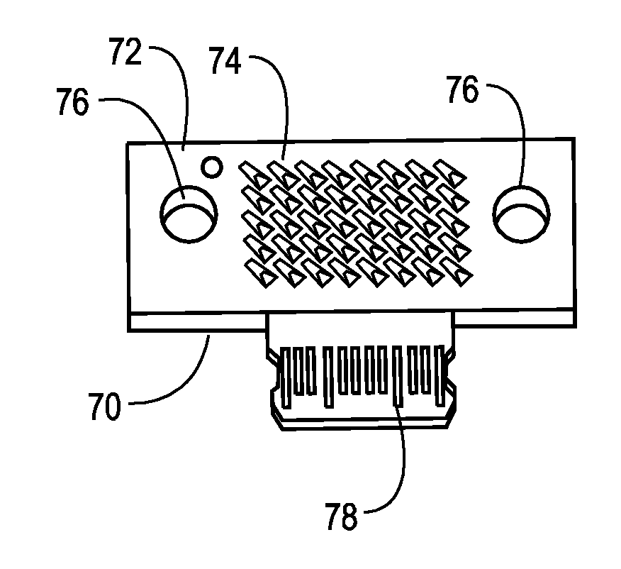
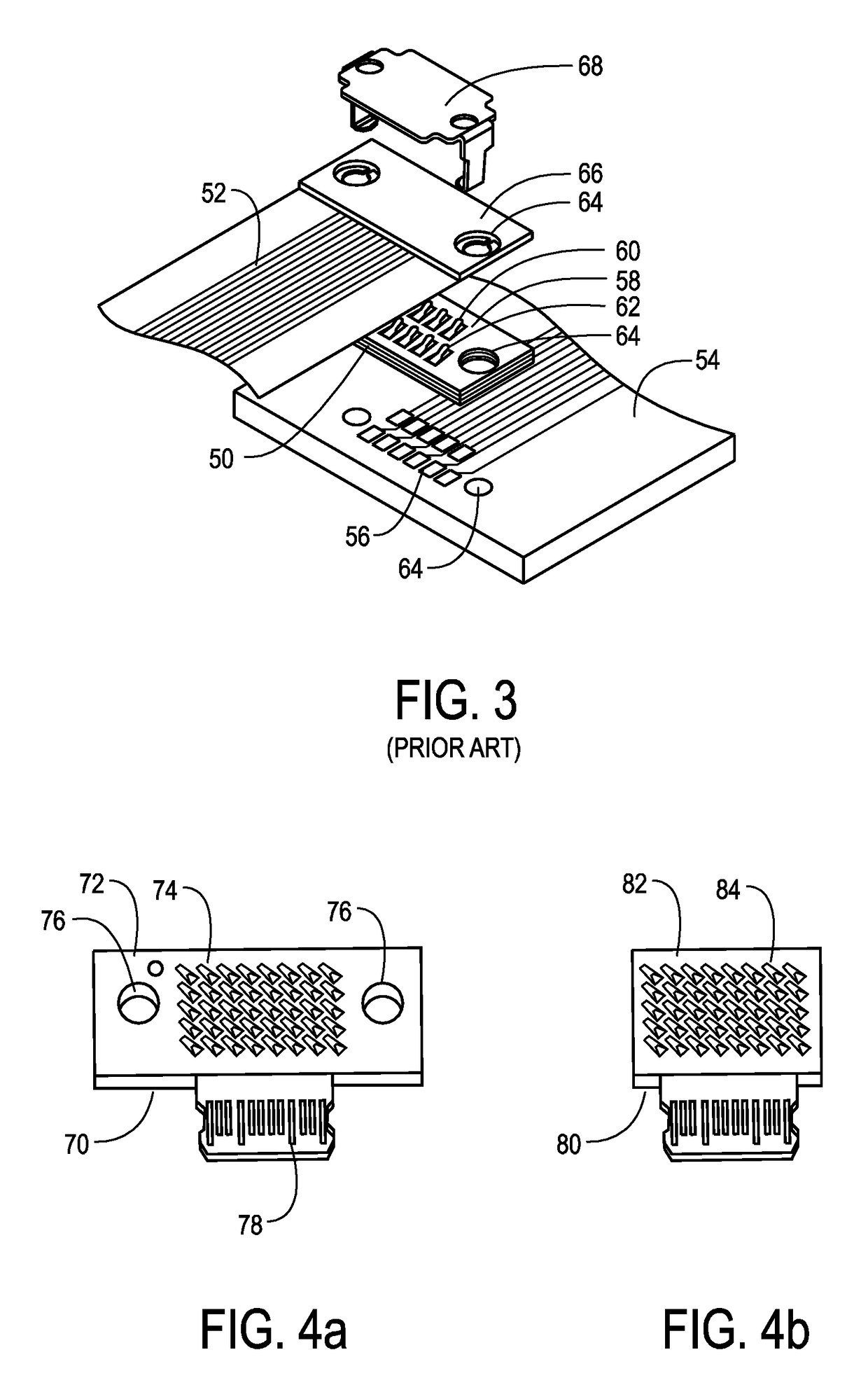
[0080]In an embodiment of the present invention, an electrical connector with a plurality of conductive spring contacts is retained on a mating circuit element, with the conductive spring contacts of the connector in a compressed state, using an adhesive material disposed between the connector surface and the mating circuit element, such that low resistance electrical interconnections between the conductive spring contacts and mating conductive terminals on the mating circuit element are obtained. In one embodiment, the connector is a normal force connector, and the low resistance electrical interconnection is achieved by applying a force on the connector normal to the surface of the mating circuit element and maintaining that force using an adhesive material. In one embodiment, the connector is a Neoconix PCBeam™ connector. In one embodiment, the electrical spring contacts in their uncompressed state stand proud of the outer surface of the adhesive material. In an embodiment, the a...


PUM


Abstract

A novel electrical connector and method of manufacture is disclosed which provides an integral attachment and retention means for the purpose of electrically and mechanically interconnecting circuit elements in electronic devices, said circuit elements including but not limited to printed circuit boards, flexible printed circuits, rigid flex circuits, semiconductor package substrates, modules, and batteries. The electrical connector of the present invention utilizes a bonding material, disposed at least between the electrical spring contact elements on a surface of the connector, to bond and retain first and second portions of the electrical connector in an actuated state on a mating circuit element whereby stable and low resistance electrical interconnections are formed and maintained between the electrical connector and interconnection terminals on the mating circuit element. This design permits the electrical connector to be low-profile and use a reduced amount of space on a circuit member such as a PCB.

Description

CROSS-REFERENCE TO RELATED PATENTS[0001]The present patent application claims the benefit of provisional patent application Ser. No. 62 / 275,720 filed Jan. 7, 2016 and entitled “Low Profile Self-Clamping Normal Force Electrical Connector and Method of Manufacture”. The specification and drawings of this provisional patent application are hereby incorporated herein by reference.BACKGROUND[0002]Field of the Invention[0003]The present invention relates to electrical connectors, including separable electrical connectors, used for the interconnection of circuit elements in products such as computers, mobile phones, tablets, laptop computers, digital cameras, medical electronics devices, optoelectronic assemblies, sensors, transducers, automotive electronic assemblies, aerospace electronic assemblies, industrial electronics, or other electronic devices, systems or subsystems, or products containing discrete electronic elements requiring electrical interconnection.[0004]Background of the In...

Claims


Application Information

Patent Timeline
IPC IPC(8): H01R4/04H05K3/32H01R13/24H01R12/52H01R12/57
CPCH01R4/04H01R12/52H05K3/326H01R13/2407H01R12/57H01R12/73H01R12/79H01R13/2442H05K1/147H05K1/189H05K2201/0311
Inventor FAN, CHIH-PENGHSIEH, CHING-HOWU, MIN-HSINGCHEN, DAVID L.MAYNARD, WOODY JAMES
Owner FAN CHIH PENG
Why Eureka
Try Eureka