Electronic device, electronic apparatus, and vehicle

Active Publication Date: 2017-07-06
SEIKO EPSON CORP +1
View PDF2 Cites 2 Cited by
  • Summary
  • Abstract
  • Description
  • Claims
  • Application Information

AI Technical Summary

Benefits of technology

[0041]According to these application examples 18 and 19, a vehicle having excellent impact resistan

Problems solved by technology

Therefore, in a case where an impact caused by dropping is applied to the oscillator, there is a problem that there is a concern about d

Method used


Image

  • Electronic device, electronic apparatus, and vehicle
  • Electronic device, electronic apparatus, and vehicle
  • Electronic device, electronic apparatus, and vehicle

Examples


first embodiment

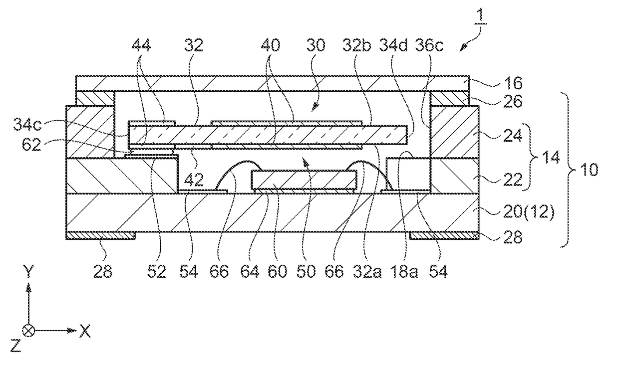
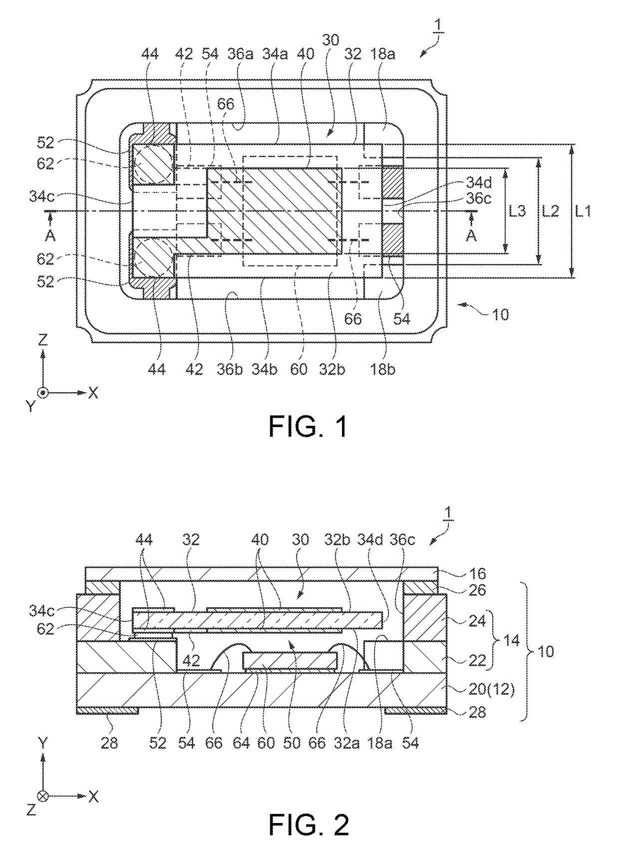
[0071]First, an example of an electronic device according to a first embodiment of the present invention will be described with reference to FIGS. 1 and 2, using an oscillator 1 provided with a vibration element 30 as an example.

[0072]FIG. 1 is a schematic plan view illustrating a structure of an oscillator according to the first embodiment of the present invention. FIG. 2 is a sectional view taken along line A-A in FIG. 1. In addition, in the following schematic plan views including FIG. 1, for convenience of description, a lid member 16 will be omitted. In addition, in each of the following drawings including FIG. 1, for convenience of description, an X-axis, a Y-axis, and a Z-axis are illustrated as three axes which are orthogonal to each other, and a tip end side and a base end side of an arrow are respectively illustrated as “+ side” and “− side” in the drawing. In addition, hereinafter, the direction parallel to the X-axis is referred to as “X-axis direction”, the direction pa...

second embodiment

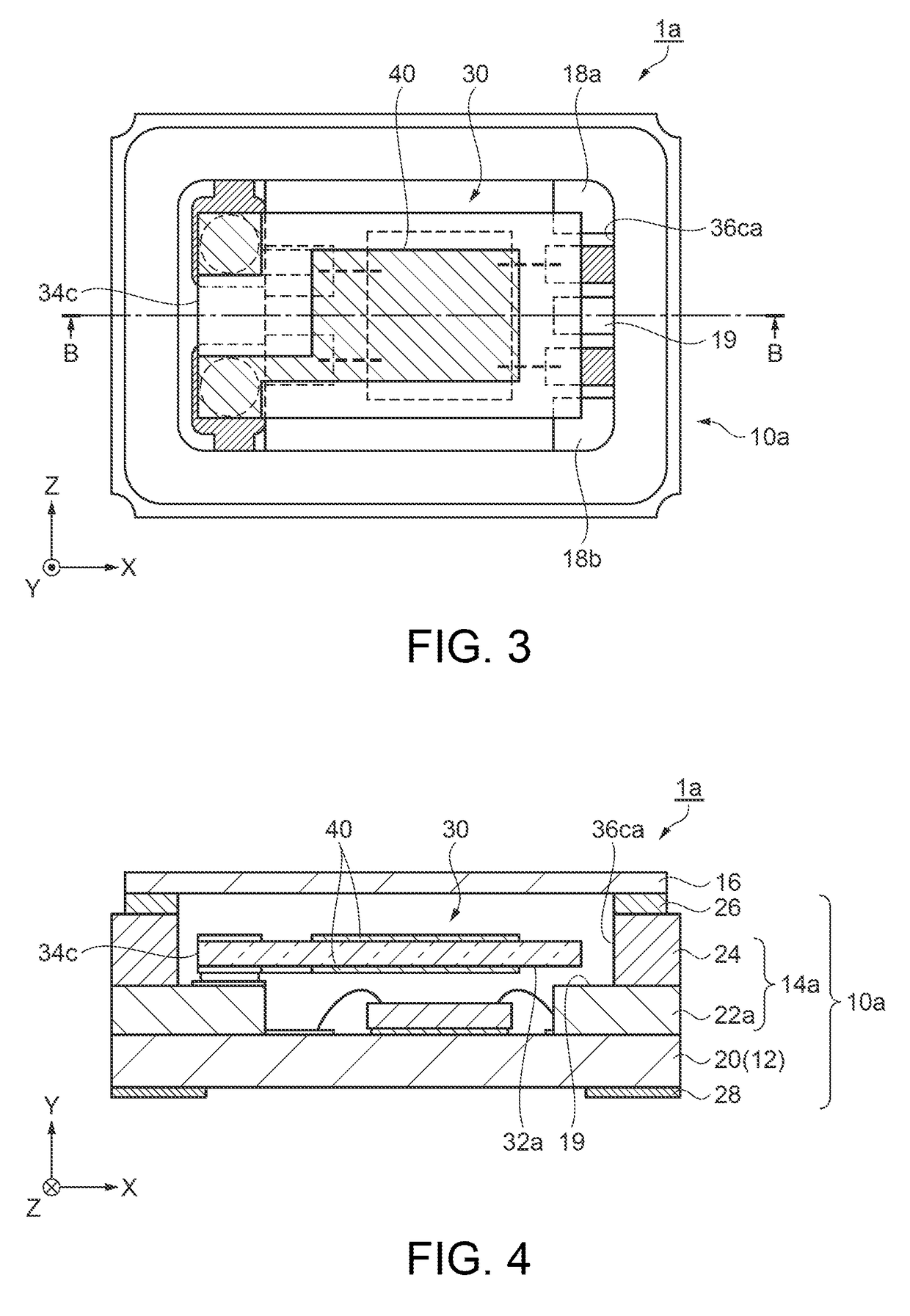
[0098]An oscillator 1a which serves as the electronic device according to a second embodiment of the present invention will be described with reference to FIGS. 3 and 4.

[0099]FIG. 3 is a schematic plan view illustrating a structure of the oscillator according to the second embodiment of the present invention. FIG. 4 is a sectional view taken along line B-B in FIG. 3.

[0100]The oscillator 1a according to the second embodiment is different from the oscillator 1 described in the first embodiment in that a third projection portion 19 which is another projection portion is disposed between the first projection portion 18a and the second projection portion 18b.

[0101]Since other configurations are substantially the same as those of the above-described oscillator 1 in the first embodiment, the oscillator 1a will be described while similar configuration elements are given the same reference numerals and numbers, and the description thereof is partially omitted.

[0102]In the oscillator 1a, as ...

third embodiment

[0104]An oscillator 1b which serves as the electronic device according to a third embodiment of the present invention will be described with reference to FIGS. 5 and 6.

[0105]FIG. 5 is a schematic plan view illustrating a structure of the oscillator according to the third embodiment of the present invention. FIG. 6 is a sectional view taken along line C-C in FIG. 5.

[0106]The oscillator 1b according to the third embodiment is different from the oscillator 1 described in the first embodiment in the shape of the vibration element 30b which is placed in the container 10.

[0107]Since other configurations are substantially the same as those of the above-described oscillator 1 in the first embodiment, the oscillator 1b will be described while similar configuration elements are given the same reference numerals and numbers, and the description thereof is partially omitted.

[0108]As illustrated in FIGS. 5 and 6, the oscillator 1b has a different shape of a vibration element 30b placed in the co...


PUM


Abstract

An electronic device includes: a container including first and second projections disposed on a bottom plate; and a vibration element having an end on a third surface side of the vibration element placed in a container via a connector so that the first and second projections, and a first surface face each other with a void therebetween, and the first and second projection portions partially overlap the first surface on a fourth surface side of the vibration element, and are aligned along the direction intersecting the longitudinal direction of the vibration element. In addition, a relationship of L1>L2>L3 is satisfied when an interval between ends in the intersecting direction is L1, an interval between the first and second projections is L2, and an interval between ends in the intersecting direction of an electrode film is L3.

Description

TECHNICAL FIELD[0001]The present invention relates to an electronic device, an electronic apparatus provided with the electronic device, and a vehicle.BACKGROUND ART[0002]The electronic device which uses a piezoelectric material, such as quartz crystal, is used in many fields as an electronic component, such as an oscillator, a vibrator, a resonator, and a filter.[0003]Among these, the oscillator is widely used in electronic apparatuses as a timing source including a time source or a control signal, a reference signal or the like. In the oscillator, a vibration element which has excitation electrodes provided on opposing main surfaces of a vibration region of the vibration element, and an electronic component which excites the vibration element and generates a stable reference frequency, are loaded in a container having an accommodation space, and the oscillator is air-tightly sealed. The vibration element is loaded in a cantilever structure of which only one end side is fixed in or...

Claims


Application Information

Patent Timeline
IPC IPC(8): H03H9/25H03B28/00H03H9/05
CPCH03H9/25H03B28/00H03H9/058H03H9/0547H03H9/1021H03H9/19H01L2224/48091H01L2224/73265H01L2924/00014
Inventor CHIBA, SEIICHI
Owner SEIKO EPSON CORP
Why Eureka
Try Eureka