Assembler for modular prosthesis

a modular prosthesis and assembly technology, applied in the field of prosthesis installation, can solve the problems of high unreliable acetabular cup implantation process, inconvenient placement of acetabular cup, and mal-alignment of cup, so as to improve site preparation, improve the effect of cutting, trimming, drilling and drilling

Active Publication Date: 2017-07-13
BEHZADI KAMBIZ
View PDF15 Cites 26 Cited by
  • Summary
  • Abstract
  • Description
  • Claims
  • Application Information

AI Technical Summary

Benefits of technology

[0012]Other embodiments include adaptation of various devices for accurate assembly of modular prostheses, such as those that include a head accurately impacted onto a trunion taper that is part of a stem or other element of the prosthesis.
[0013]Still other embodiments include an alignment system to improve site preparation, such as, for example, including a projected visual reference of a desired orientation of a tool and then having that reference marked and available for use during operation of the tool to ensure that the alignment remains proper throughout

Problems solved by technology

Even though hip replacement surgery has been one of the most successful operations, it continues to be plagued with a problem of inconsistent acetabular cup placement.
Cup mal-positioning is the single greatest cause of hip instability, a major factor in polyethylene wear, osteolysis, impingement, component loosening and the need for hip revision surgery.
These incorporated patents explain that the process of cup implantation with a mallet is highly unreliable and a significant cause of this inconsistency.
The patents note two specific problems associated with the use of the mallet.
First is the fact that the

Method used


Image

  • Assembler for modular prosthesis
  • Assembler for modular prosthesis
  • Assembler for modular prosthesis

Examples


embodiment 500

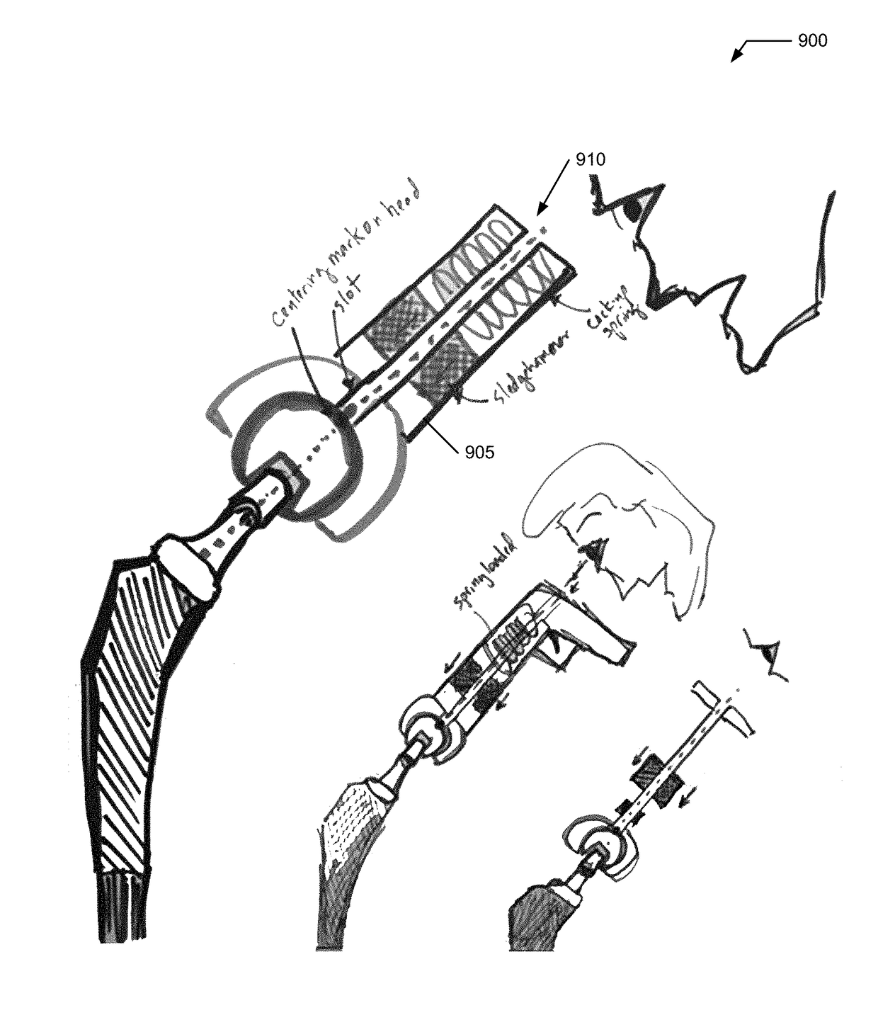
[0070]FIG. 5 illustrates an alternative embodiment 500 to the devices of FIG. 1-4 including a pressure sensor 505 to provide feedback during installation. With respect to management of the force required for some of these tasks, it is noted that with current techniques (the use of the mallet) the surgeon has no indication of how much force is being imparted onto the implant and / or the implant site (e.g., the pelvis). Laboratory tests may be done to estimate what range of force should be utilized in certain age groups (as a rough guide) and then fashioning a device 500, for example a modified sledgehammer 100 or cockup gun 300 to produce just the right amount of force. Typically the surgeon may use up to 2000N to 3000N of force to impact a cup into the acetabular cavity. Also, since some embodiments cannot deliver the force in an incremental fashion as described in association with the BMD3 device, device 500 includes a stopgap mechanism. Some embodiments of the BMD3 device have alre...

first embodiment

[0103]FIG. 14 illustrates a first embodiment for a BMD5 tool 1400 used in cooperation with assembly of modular prosthesis 700 to install head 710 onto trunion taper 715 at an end of stem 720. Prosthesis 700 is modified to include a grip structure 1405 (e.g., an indentation, hole, cavity, aperture, and the like) to allow engagement of a retention structure (e.g., a claw, grasper, gripper, and the like—represented by G) coupled to both tool 1400 and to prosthesis 700. Optional grip structure 1405 may be used to reduce or eliminate wasting of kinetic energy during assembly and welding of head 710 onto taper 715.

[0104]BMD5 tool 1400 includes a head grasper 1410, an in-line force sensor module 1415, a torquer 1420, and torque converter 1425. Head grasper 1410 retains and aligns head 710 into an optimum installation orientation (e.g., perpendicular / normal) to allow application of force only along an assembly axis 1430 joining, and aligned with, grip structure 1405, head 710, taper 715, gr...

second embodiment

[0111]FIG. 15 illustrates a second embodiment for a BMDS tool 1500 used in cooperation with assembly of modular prosthesis 700 to install head 710 onto trunion taper 715 at an end of stem 720. Tool 1500 varies from tool 1400 in that tool 1500 performs insertion using a vibration profile. The vibration profile is provided by a vibration engine 1505 that may include a rotary motor 1510 coupled to a linear motion converter 1515 to impart a vibration to head grasper 1410 (and then to head 710) to insert and cold weld head 710 onto trunion taper 715. There are other ways to implement vibration engine 1505.

[0112]In operation, tool 1500 may join head 710 to taper 715 with a vibratory force (implicating a blend of static and kinetic coefficients of friction—Us and Uk), which may require less force than a series of discrete / dynamic impacts onto head 710.


PUM


Abstract

A system and method for improving installation of a prosthesis. Devices include prosthesis installation tools, prosthesis assembly tools, site preparation systems, and improved power tools used in implant site preparation.

Description

CROSS REFERENCE TO RELATED APPLICATIONS[0001]This application in a continuation-in-part of U.S. patent application Ser. No. 15 / 202,434, filed 5 Jul. 2016 that in turn claims benefit of U.S. Patent Application No. 62 / 277,294, both of which are hereby expressly incorporated by reference in their entireties for all purposes.FIELD OF THE INVENTION[0002]The present invention relates generally to installation of a prosthesis, and more specifically, but not exclusively, to improvements in prosthesis placement and positioning.BACKGROUND OF THE INVENTION[0003]The subject matter discussed in the background section should not be assumed to be prior art merely as a result of its mention in the background section. Similarly, a problem mentioned in the background section or associated with the subject matter of the background section should not be assumed to have been previously recognized in the prior art. The subject matter in the background section merely represents different approaches, which...

Claims


Application Information

Patent Timeline
IPC IPC(8): A61F2/46A61F2/34A61B17/92A61F2/36
CPCA61B17/92A61F2/34A61F2002/30604A61F2002/3611A61F2002/3625A61F2002/365A61B2017/925A61F2002/4623A61F2002/4632A61F2002/4681A61F2002/4666A61F2/4607A61F2/3609A61F2/3662A61F2/4609A61F2/4657A61B17/1666A61B17/142A61F2002/30565A61F2002/469A61F2002/4694A61B34/20A61F2/4637A61F2002/30525A61F2002/30617A61F2002/30718A61F2002/3627A61F2002/4627A61F2002/4629A61F2002/4671A61F2250/006A61F2002/4688A61F2002/4687A61F2/4603
Inventor BEHZADI, KAMBIZ
Owner BEHZADI KAMBIZ
Why Eureka
Try Eureka