
Micromechanical pressure sensor

a pressure sensor and micro-mechanical technology, applied in the direction of fluid pressure measurement, instruments, coatings, etc., can solve the problems of potting die sealing, easy damage to the membrane, complicated and cost-intensive,

Active Publication Date: 2017-07-13
ROBERT BOSCH GMBH
View PDF5 Cites 0 Cited by
  • Summary
  • Abstract
  • Description
  • Claims
  • Application Information

AI Technical Summary

Benefits of technology

The patent describes a method for making a pressure sensor by attaching both the sensor element and the evaluation circuit to a substrate using a single placement process. A potting die is used to seal off the depression where the sensor element is located, preventing potting compound from entering this area and potentially contaminating or overloading the sensor. The potting compound protects the sensor element and is particularly useful in automotive applications. Overall, the method provides a reliable and efficient way to create pressure sensors.

Problems solved by technology

Electric contacts between said elements then still have to be passivated, which can be complicated and cost-intensive.
It is disadvantageous in this connection that the potting die has to be sealed off from the membrane of the sensor element.
In the process, the membrane may easily be damaged or the tightness in relation to the potting compound cannot be ensured.

Method used


Image

  • Micromechanical pressure sensor
  • Micromechanical pressure sensor
  • Micromechanical pressure sensor

Examples


Embodiment Construction

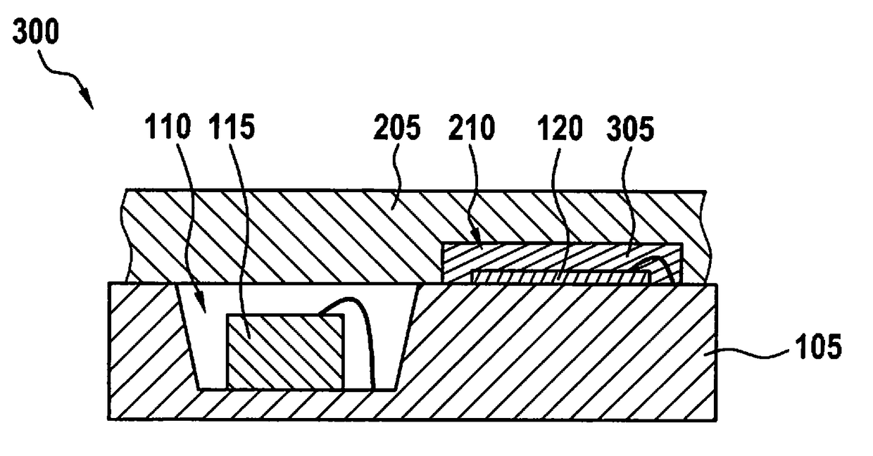
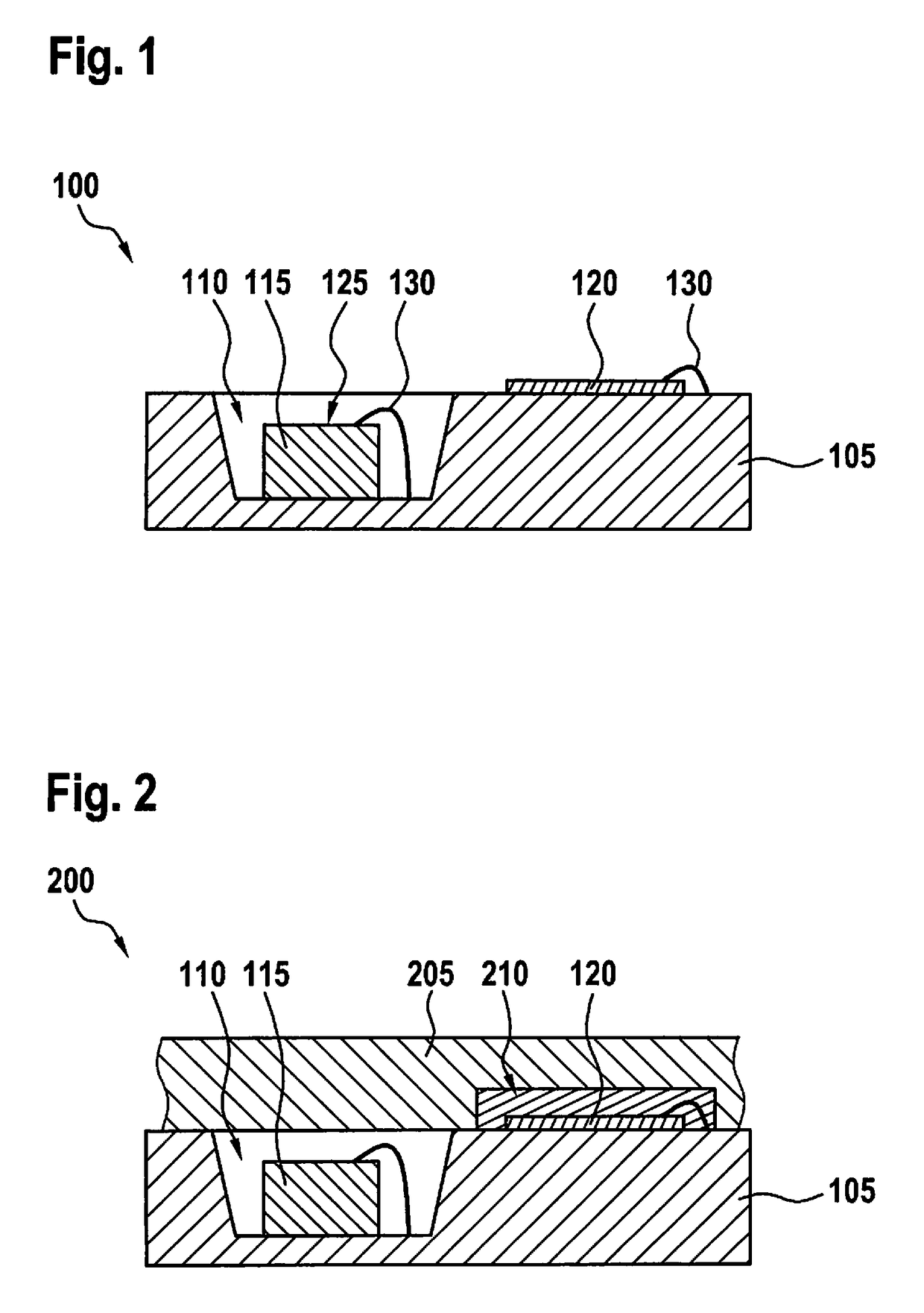
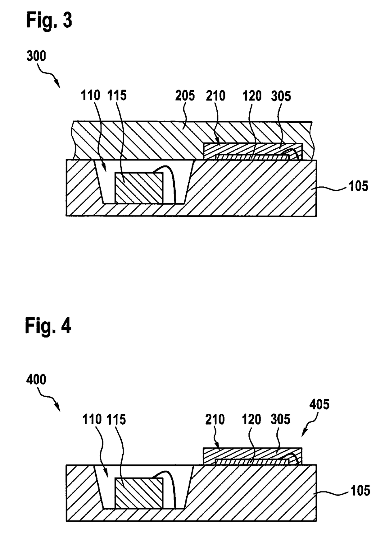
[0015]FIG. 1 shows a first step 100 of a method for producing a pressure sensor. A substrate 105 comprises a depression 110 which may also be called a cavity. The substrate 105 customarily comprises a semiconductor material, for example silicon. On an upper surface of the substrate 105, a micromechanical sensor element 115 is attached in the depression 110 and an evaluation circuit 120 is attached next to the depression 110. The micromechanical sensor element 115 comprises a micromechanical structure (MEMS: Microelectromechanical System) which comprises a membrane 125 which is mounted movably in relation to the rest of the sensor element 115. The evaluation circuit 120 is customarily a semiconductor circuit which is generally designed as an application-specific integrated circuit (ASIC). The sensor element 115 and the evaluation circuit 120 are customarily fastened to the membrane 125 with an adhesive bonding technique.

[0016]Electrical connections between the sensor element 115 and ...


PUM

PropertyMeasurementUnit
timeaaaaaaaaaa
semiconductoraaaaaaaaaa
conductiveaaaaaaaaaa

Abstract

A method for producing a pressure sensor comprises providing a substrate with a depression; attaching a micromechanical sensor element to the substrate in the depression; attaching an evaluation circuit to the substrate next to the depression; electrically connecting the evaluation circuit to the sensor element; covering the substrate around the depression by means of a potting die such that the depression is closed; potting the evaluation circuit between the substrate and the potting die; and removing the potting die.

Description

CROSS REFERENCE[0001]The present application claims the benefit under 35 U.S.C. §119 of German Patent Application No. DE 102016200263.5 filed on Jan. 13, 2016, which is expressly incorporated herein by reference in its entirety.FIELD[0002]The present invention relates to a micromechanical pressure sensor. In particular, the present invention relates to the production of the pressure sensor from semiconductor components.BACKGROUND INFORMATION[0003]A pressure sensor comprises a micromechanical sensor element and an evaluation circuit, which are arranged in a common housing. The housing protects the individual components against environmental influences, such as dust, vibration and heat, and therefore the pressure sensor can be used, for example, on board a motor vehicle. The micromechanical sensor element comprises a membrane, the deformation or deflection of which because of atmospheric pressure is converted into a sensor signal which is then further processed by means of the evaluat...

Claims


Application Information

Patent Timeline
Patent Type & Authority Applications(United States)
IPC IPC(8): B81C1/00
CPCB81C1/00333B81C2203/0136B81C2203/0154B81C2203/0792B81B7/0032B81C1/0023B81C1/00269G01L7/08B81C1/00309B81B2201/0264B81B2207/012G01L19/141B81B7/0061
Inventor GRABMAIER, FLORIANSCHELLKES, ECKARTLINDEMANN, TIMO
Owner ROBERT BOSCH GMBH
Learn More