
Load transmission device

a transmission device and load technology, applied in the direction of paving details, structural elements, building components, etc., can solve the problem and achieve the effect of reducing environmental impa

Active Publication Date: 2017-07-13
MOREIRA SERRO AFONSO
View PDF2 Cites 1 Cited by
  • Summary
  • Abstract
  • Description
  • Claims
  • Application Information

AI Technical Summary

Benefits of technology

The patent describes a type of concrete that is resistant and easy to control, with high mechanical strength. This is achieved by using telescopic bars and optimized prefabricated ribbing. The use of these concrete roads reduces environmental impact, as the constituent elements do not release pollutants during manufacture or placement and use.

Problems solved by technology

Additionally, the possibility of obtaining concrete roads with these telescopic bars, and the fact that the constituent slabs can be prefabricated, remarkably reduces the environmental impact since the constituent elements do not release pollutants, neither in the manufacture nor in the application and use.

Method used


Image

  • Load transmission device
  • Load transmission device
  • Load transmission device

Examples


first embodiment

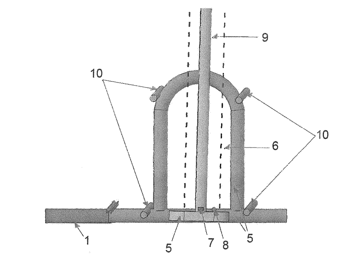
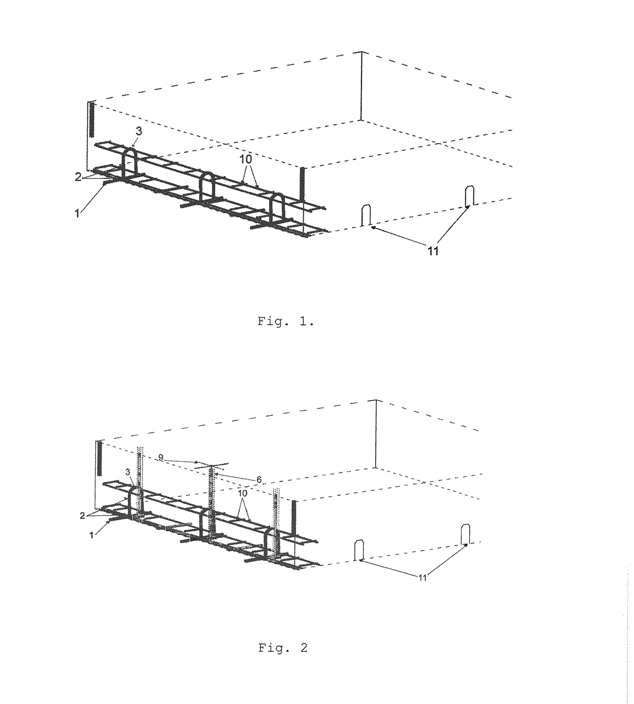
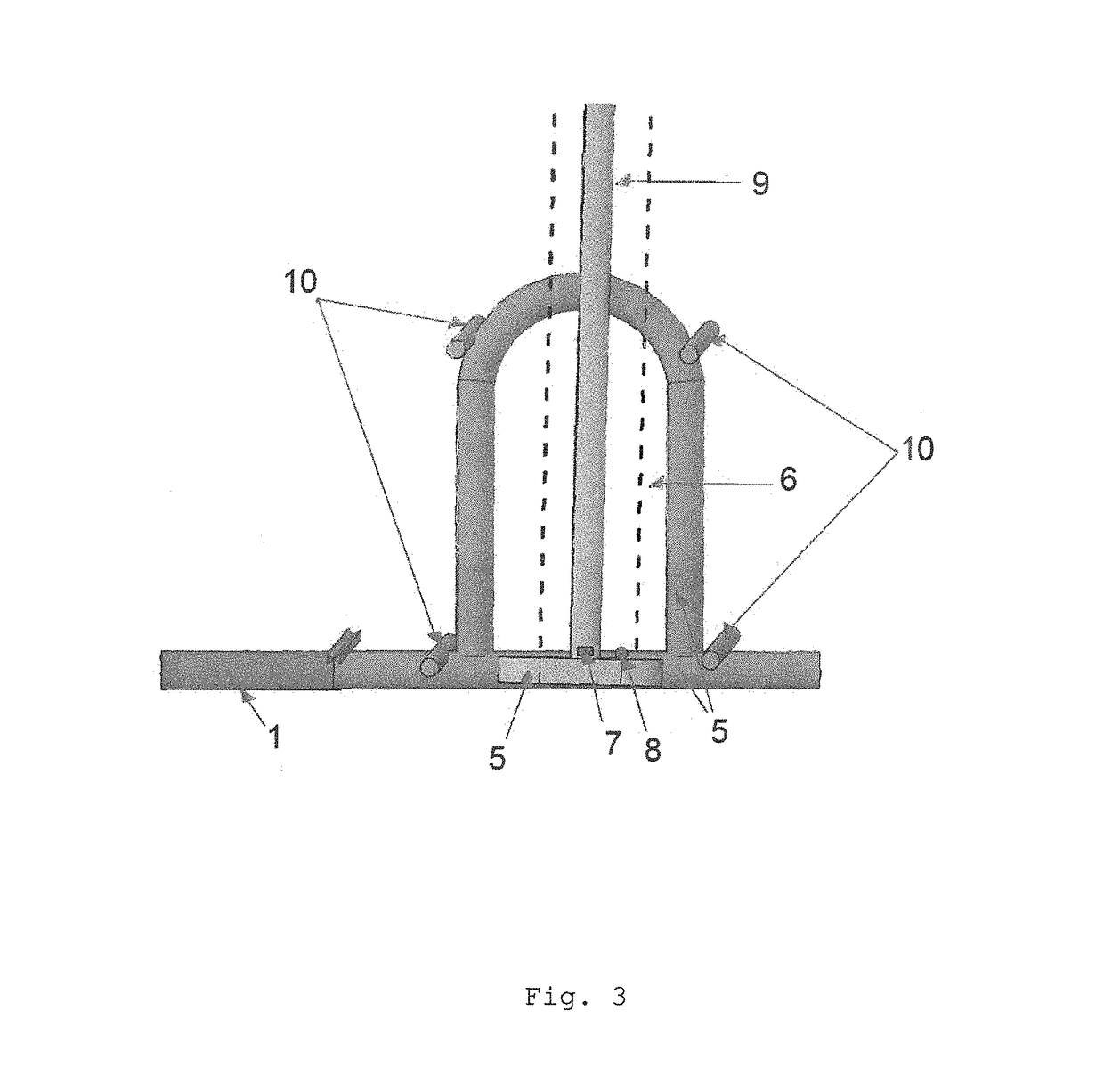
[0061]In a first preferred embodiment of the invention, the fabrication of the slabs in bend molds is pre-defined, i.e. a perfect planimetry is maintained even when the over-elevation bend of the curves is marked. In summary, in a first embodiment the bar (1) is provided with an anchoring arc or bar (3) with fixed curvature.

[0062]In a second preferred embodiment of the invention, the telescopic bars for load transmission (1) are constituted by a single piece which is anchored to the slab in the same position and alignment, and which accepts the acceptance sheaths of the adjoining slab, maintaining the same type of function as the telescopic bar.

[0063]In a third preferred embodiment of the invention, the bars (1) may rotate about an axis with a limited travel, in which a bar already pre fixed in an acceptance slab and the extension of the sane is inserted in a sheath which is screwed to a rigid base, anchored in the adjoining slab. This bar (1) is placed on top of the slab and allows...

third embodiment

[0064]In a fourth preferred embodiment of the invention, the bars (1) are executed in a similar way as the third embodiment, however they have larger dimensions and are placed laterally along the thickness of the slab, where access to the top of the slab is difficult or does not allow the filling of the attachment zone of the acceptance sheaths, due to the excessive abrasion.


PUM


Abstract

The present invention relates to bars for load transmission, which if anchored in concrete slabs create a support between them, forming semi-rigid joints and accompanying the differential settlements of the foundation bed, as a result of the rotation in the vertical direction about the joint axis, and transmitting the load from a slab to the other, ensuring a perfect leveling of the surface thereof when occurring elastic movements of the foundations, and allowing the possibility of removing the slabs at any time and reuse them again, due to the telescopic effect of the bars. The telescopic function of the bar which allows its support between slabs created a new possibility of obtaining prefabricated floorings of easy manufacture and assembly in situ, creating a new concept in the construction of roads, ports, airports, railways, industrial areas, etc., which distinguishes the present invention from the closest state of the art.

Description

FIELD OF THE INVENTION[0001]The scope of the present invention is the construction and public works, namely construction with concrete and specifically construction of roads and highways, ports, airports, railways and industrial areas.TECHNICAL BACKGROUND OF THE INVENTION[0002]The following patent documents were identified through a research on the prior art in the field of the invention:[0003](D1) The CN 1800540 A-D1 describes a hollow reinforced concrete slab comprising hollow elements of reinforced concrete. The elements are concreted “in situ” and reinforced with a concrete rib. The hollow elements comprise a formwork cavity. The invention can be applied to various solutions of molded and reinforced concrete, such as roofs of buildings, foundation slabs, walls and bridges;[0004](D2) CN 203401620 U-D2 is a utility model which discloses a connector for steel bars and is designed with the objective of solving the problems associated with the reinforcing steel bars, which may includ...

Claims


Application Information

Patent Timeline
Patent Type & Authority Applications(United States)
IPC IPC(8): E01C11/14E04C5/00E01C5/00
CPCE01C11/14E01C5/06E04C5/00E01C5/005E04B1/41E04B1/4171E04B2001/4192E01C2201/12E04B5/023E04C5/18E04C5/205E04B1/483
Inventor LOUREN O SERRO, MANUEL FILIPE
Owner MOREIRA SERRO AFONSO
Learn More