Floor drain

a floor drain and drain pipe technology, applied in the field of floor drains, can solve the problems of inability to inspect the connection between the feed of the heat exchanger tube the conduit for cold mains water, significant amount of unused energy loss, and undesirable discharge of hot waste water without recovery

Inactive Publication Date: 2017-07-13
RECALOR
View PDF2 Cites 14 Cited by
  • Summary
  • Abstract
  • Description
  • Claims
  • Application Information

AI Technical Summary

Benefits of technology

[0009]The subject of the present invention is to

Problems solved by technology

The accumulated heat in the water is thus not exploited completely before it is led out into a floor drain and thereby a significant amount of unused energy is lost.
In terms of efficient use of energy it is undesirable to discharge hot waste water without recovering the energy present in the waste water.
One drawback is that it is impossible to inspect the connection between the heat exchanger tube's feed for cold mains water and the conduit for cold mains water and the connection between the tube's discharge and the mixer tap when the floor drain is installed in a floor of a building.
Yet another drawback is that if these connections get damaged it results in water leakage in the floor in which the floor drain is installed.
A further drawback is that it is difficult and time consuming to in

Method used


Image

  • Floor drain
  • Floor drain
  • Floor drain

Examples


Embodiment Construction

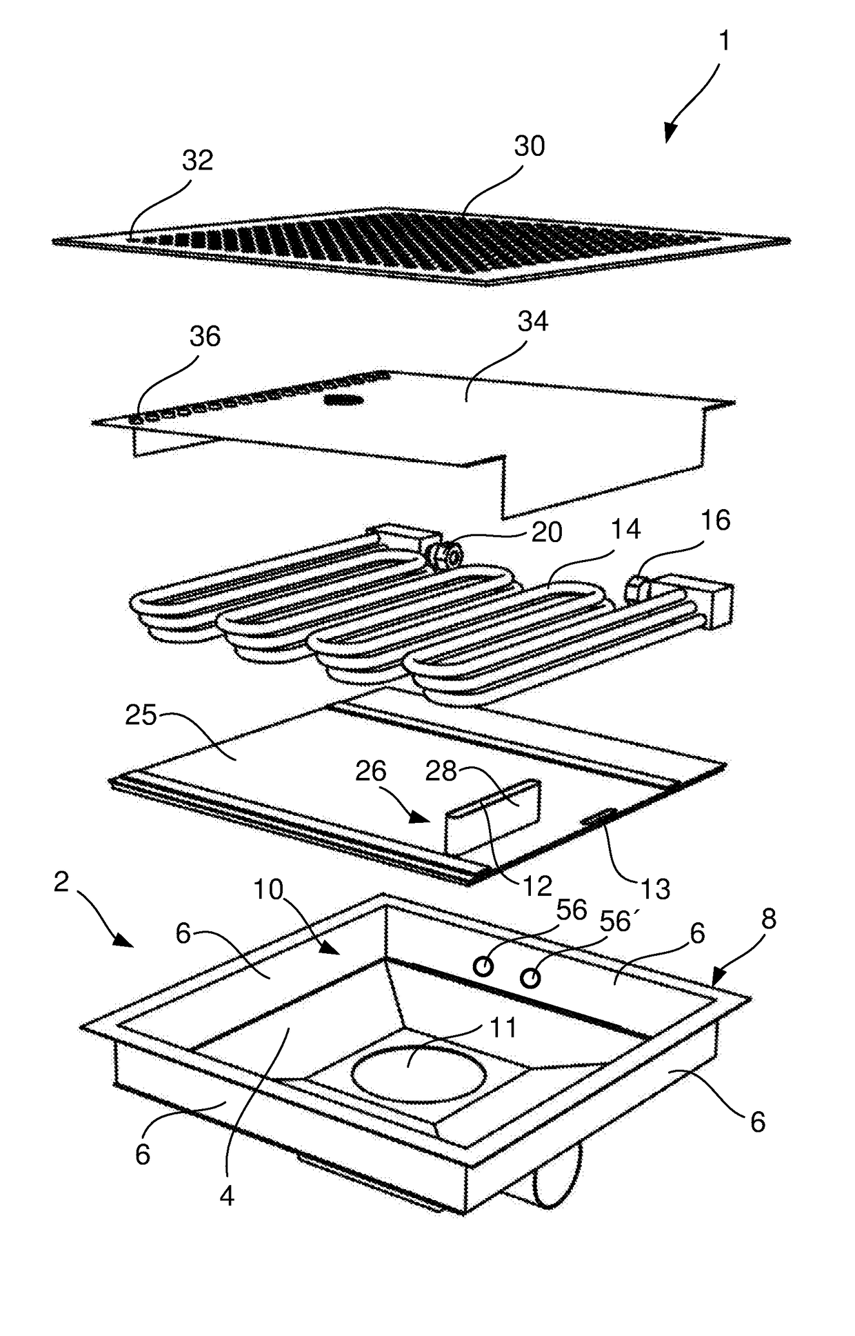
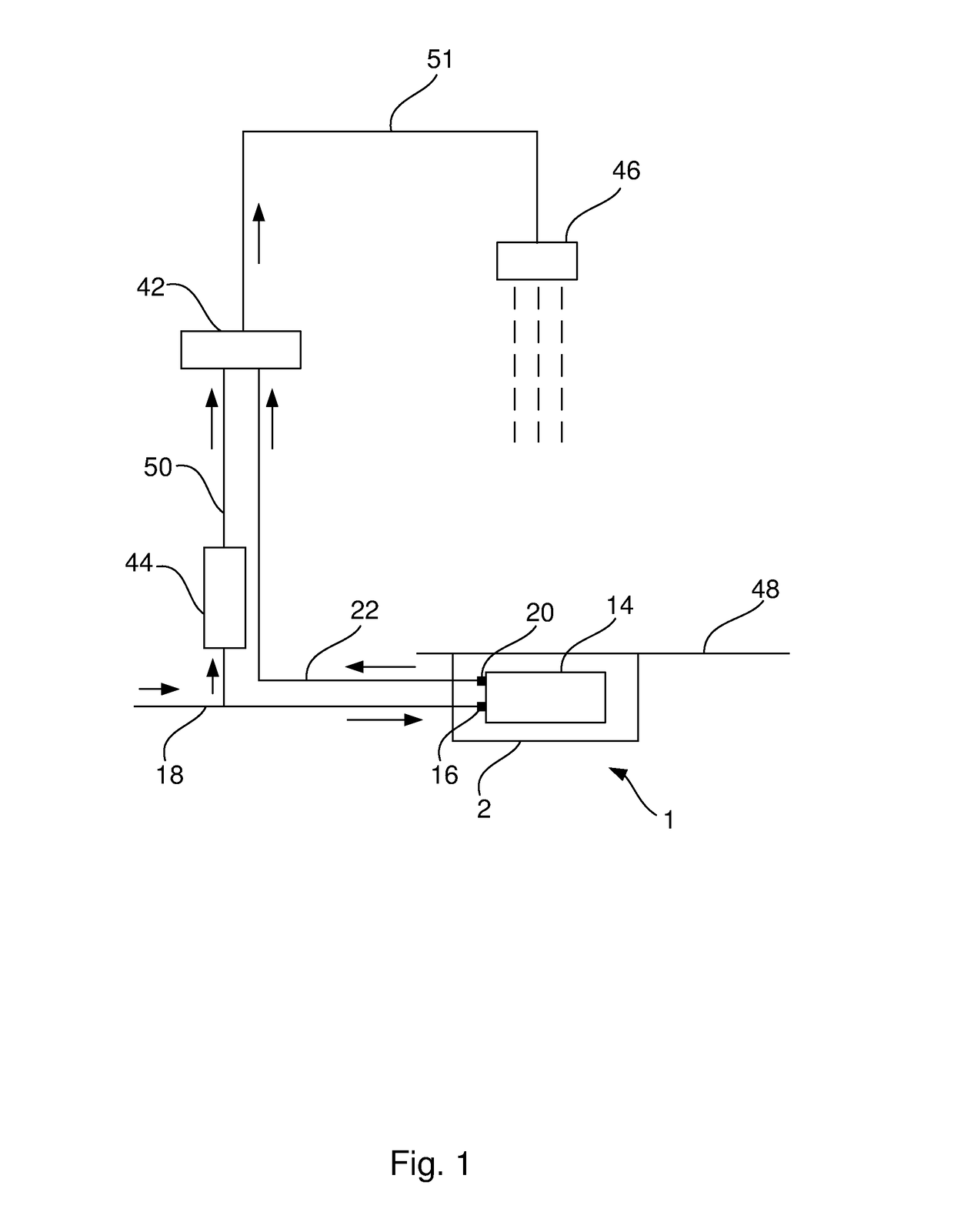
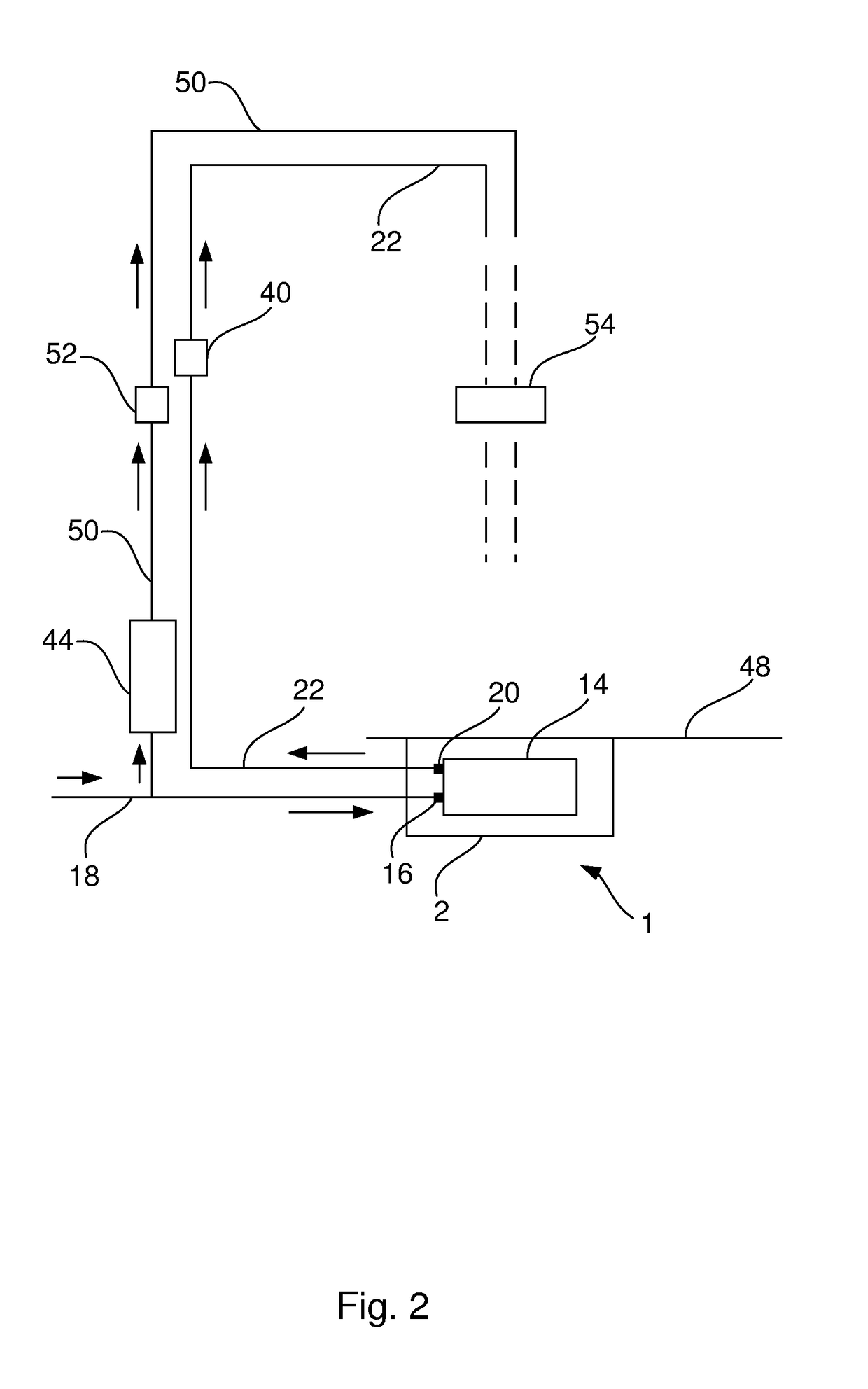
[0035]FIG. 1-4 show schematic views illustrating the effect obtained by using the floor drain 1 according to the present invention. In FIG. 1-4, the dashed lines are water and the straight arrows show the direction of the water flow. A shower is shown in FIG. 1-4. It is also possible to use the floor drain 1 together with a bath tub, a washing machine, a dish washer or any other appliance where hot and cold water are to be mixed just before use. The effect will first be described with reference to FIG. 1.

[0036]A shower head 46 is arranged above the floor drain 1 which is arranged in a floor 48. The definition of a “floor drain” is a drain that is installed in a floor so that the top of the floor drain is substantially in the same level as the floor surface. The floor drain 1 comprises a heat exchanger element 14 arranged inside a drain compartment 2. The heat exchanger element 14 is connected with a first connection 16 to a first conduit 18 for fresh water having a first temperature...


PUM


Abstract

The invention relates to a floor drain comprising a drain compartment having a bottom, at least one side and an open upper portion. The bottom and the at least one side together define a space to collect waste water. The bottom comprises an opening for a drain trap. The floor drain further comprises a heat exchanger element, receivable in the space of the drain compartment, for transferring heat present in the waste water to fresh water. The heat exchanger element is provided with a first connection and a second connection. The first connection and the second connection are arranged inside the space of the drain compartment. A first conduit is connected to the first connection and a second conduit is connected to the second connection.

Description

CROSS REFERENCE TO RELATED APPLICATIONS[0001]This application is a U.S. National Stage patent application of International Patent Application No. PCT / SE2015 / 050528, filed on May 12, 2015, which claims priority to Swedish Patent Application No, 1450630-7, filed on May 27, 2014, each of which is hereby incorporated by reference in the present disclosure in its entirety.FIELD OF THE INVENTION[0002]The present invention relates to a floor drain according to the preamble of claim 1.BACKGROUND OF THE INVENTION[0003]Usually, hot water discharge from appliances where hot and cold water are to be mixed just before use, for example showers and bath tubs, is led directly into floor drains without a substantial drop of temperature in the water. The accumulated heat in the water is thus not exploited completely before it is led out into a floor drain and thereby a significant amount of unused energy is lost. In terms of efficient use of energy it is undesirable to discharge hot waste water witho...

Claims


Application Information

Patent Timeline
IPC IPC(8): F28D21/00E03C1/22F24D17/00E03F5/04F28D3/02
CPCF28D21/0012E03F5/0408F28D3/02F24D2220/06E03C1/22E03C2001/005F24D2200/20F24D17/0052Y02B10/70E03C1/00F28D7/082Y02B30/18Y02B30/56
Inventor TORNQUIST, LARSTORNQVIST, HANS
Owner RECALOR
Why Eureka
Try Eureka