Inverter apparatus for polyphase ac motor drive

Active Publication Date: 2017-07-13
MITSUBISHI ELECTRIC CORP
View PDF7 Cites 8 Cited by
  • Summary
  • Abstract
  • Description
  • Claims
  • Application Information

AI Technical Summary

Benefits of technology

[0012]According to the invention, inserting a separate power supply switching device into each phase allows isolating the faulty phase and continuing motor drive only with the remaining phases,

Problems solved by technology

Indeed, quickly stopping the motor would be a measure against an overall systematic failure, but, stopping the motor caus

Method used


Image

  • Inverter apparatus for polyphase ac motor drive
  • Inverter apparatus for polyphase ac motor drive
  • Inverter apparatus for polyphase ac motor drive

Examples


Example

First Embodiment

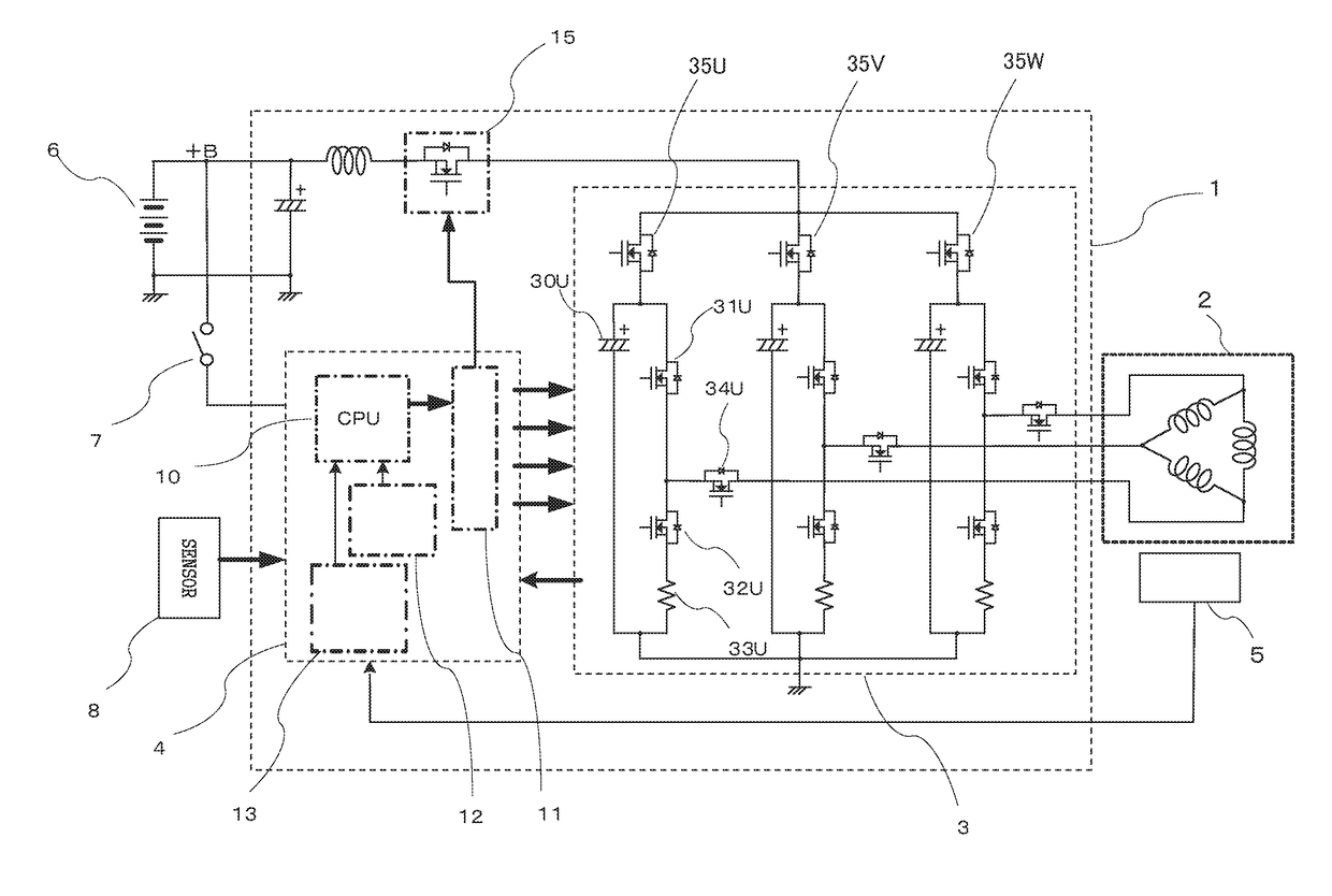
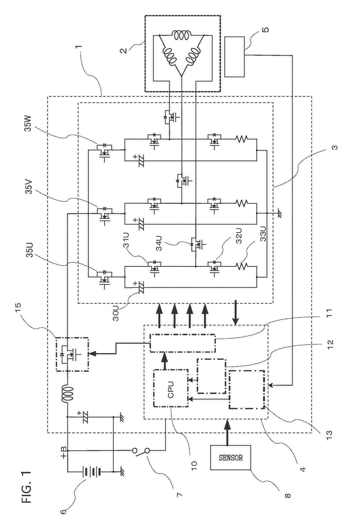
[0018]FIG. 1 is an overall configuration circuit diagram of an electrically assisted power steering apparatus including an inverter apparatus of a first embodiment of the invention. In the electrically assisted power steering apparatus, an inverter apparatus 1 is configured to supply current to a motor 2 from a power source 6 loaded in a vehicle.

[0019]The inverter apparatus 1 includes an inverter circuit 3 and a control circuit 4. A rotation sensor 5 is provided to the motor 2. Information detected by the rotation sensor 5 is input to the control circuit 4. Between the power source 6 and the inverter circuit 3, an ignition switch 7 for starting the operation of the control circuit 4, a capacitor and coil as a noise measure in the power supply line (+B, −Ground) of the power source 6, and a first power supply switching device 15 having a relay function for switching ON / OFF current to the inverter circuit 3 are provided. The first power supply switching device 15 is, f...

Example

Second Embodiment

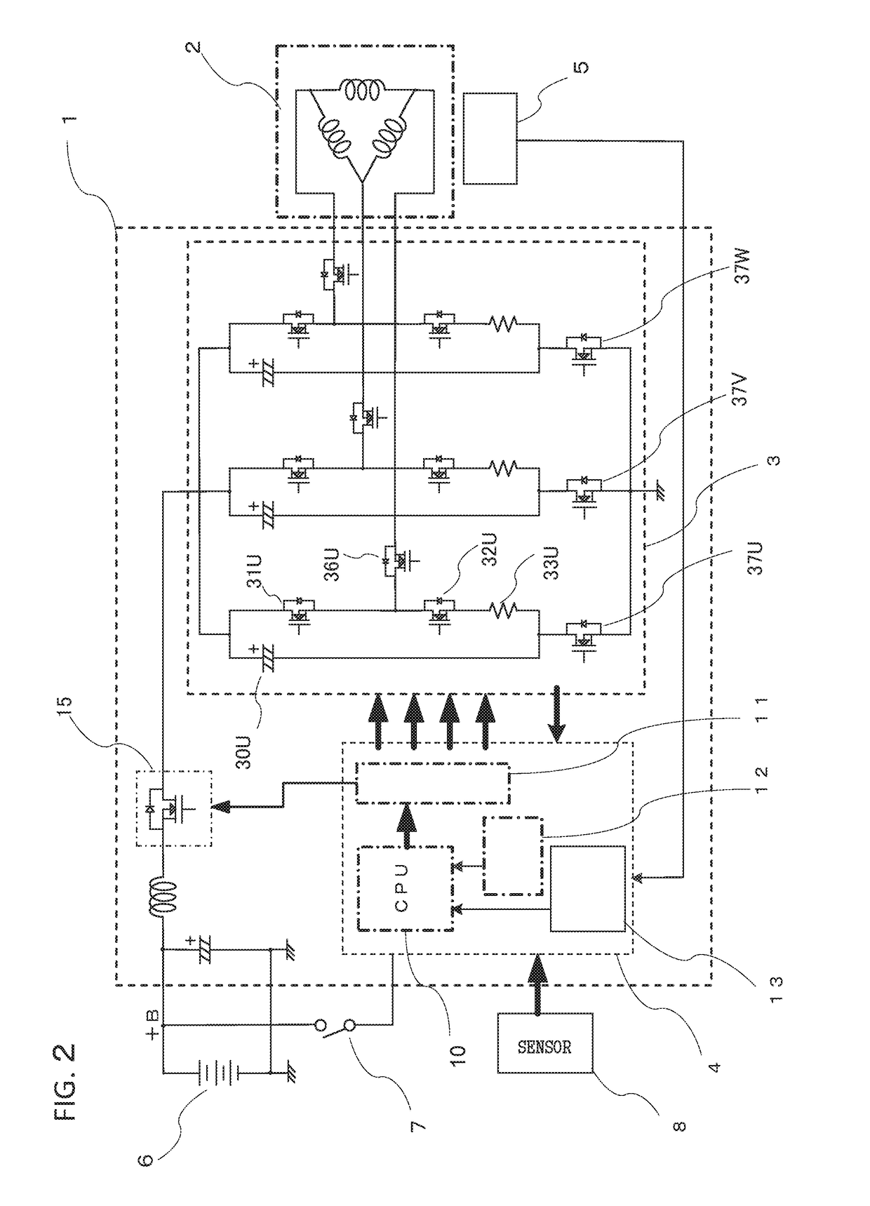
[0029]Next, a second embodiment is described with reference to FIG. 2. FIG. 2 of the second embodiment is different from FIG. 1 of the first embodiment in that the position of a second power supply switching device 37U provided in the inverter circuit 3 is different from that of the second power supply switching device 35U of FIG. 1, and the direction of the parasitic diode of a motor relay switching device 36U is different from that of the parasitic diode of the motor relay switching device 34U of FIG. 1. The remaining parts are the same, so they are denoted by the same reference numerals.

[0030]The second embodiment is configured so that the same goal or task results in the same effect when the parasitic diode of the motor relay switching device 36U is in the reverse direction with respect to the first embodiment. Also in the second embodiment, as with the first embodiment, if a short-circuit occurs in either the switching device 31U or 32U for the upper or lower a...

Example

Third Embodiment

[0033]Next, a configuration including one shunt resistor 33 for current detection is described. Even with only the one shunt resistor 33, the operation may be considered to be similar to the first and second embodiments. Also, depending on the location of the second power supply switching device 35U, 37U, two types of configurations may be considered. FIG. 3 and FIG. 4 are partial circuit diagrams showing the two types of configurations with the one shunt resistor 33 and the second power supply switching device 35 or 37.

[0034]FIG. 3 shows the first embodiment in which the second power supply switching devices 35 are placed upstream of the arm circuit of the inverter circuit 3. The one shunt resistor 33 placed downstream of and connected to the three phases of switching devices 32 of the lower arm circuit. Furthermore, the minus (−) terminals of the capacitors 30 are connected to the ground line downstream of the shunt resistor so that even if a short-circuit occurs i...


PUM


Abstract

In view of the problem that an existing technique can detect a failure in an arm circuit for each phase and continue motor drive by only a normal phase, but a brake torque is generated due to a closed circuit of the faulty phase, an inverter apparatus for polyphase AC motor drive is provided that includes: a first power supply switching device in a power supply line to an inverter circuit; a second power supply switching device for each phase in the arm circuit of the inverter circuit, and a motor relay switching device in an output path from each phase, wherein the parasitic diodes of the first power supply switching device and second power supply switching device have directional characteristics different from each other, which prevent generation of a closed circuit.

Description

TECHNICAL FIELD[0001]The present invention relates to inverter apparatuses for polyphase AC motor drive, and particularly relates to an inverter apparatus for polyphase AC motor drive that can address a failure occurring in an inverter circuit.BACKGROUND ART[0002]A polyphase AC motor is used in various applications, including an electrically assisted power steering apparatus. The power supplied to the polyphase AC motor is controlled by an inverter apparatus for polyphase AC motor drive. The following explanation takes a three-phase AC motor as an example of the polyphase AC motor. An electrically assisted power steering apparatus reduces the required steering torque applied by a driver, which is configured by combining a power source, a motor, a sensor, an inverter apparatus for three-phase AC motor drive and a controller, and which is a system that uses the sensor to detect the direction and amount of the rotation angular velocity of a steering torque applied by the driver, then u...

Claims


Application Information

Patent Timeline
IPC IPC(8): H02P29/024H02M1/084H02M7/537H02P27/08H02P6/16
CPCH02P29/0243H02P27/08H02M1/084H02M7/537H02P6/16B62D5/0484H02P29/027H02H7/08H02H7/1225H02M7/5387H02P29/032H02M1/325
Inventor KAWANO, YUOKANOUE, TAKAHIRO
Owner MITSUBISHI ELECTRIC CORP
Why Eureka
Try Eureka