Vehicle camera with connector system for high speed transmission

a technology of high-speed transmission and connector system, which is applied in the field of vehicle vision system, can solve the problems of reducing design flexibility and increasing cost, and achieve the effects of enhancing electrical connection, enhancing grounding, and enhancing electrical connection

Active Publication Date: 2017-07-13
MAGNA ELECTRONICS
View PDF2 Cites 62 Cited by
  • Summary
  • Abstract
  • Description
  • Claims
  • Application Information

AI Technical Summary

Benefits of technology

[0004]The present invention provides a vision system or imaging system for a vehicle that utilizes one or more cameras (preferably one or more CMOS cameras) to capture image data representative of images exterior of the vehicle, and provides enhanced electrical connection between a coaxial connector and circuitry of a printed circuit board of the camera. The connection of the present invention provides a ground clamp

Problems solved by technology

This method of connection to the PCB requires intricate machining, casting

Method used


Image

  • Vehicle camera with connector system for high speed transmission
  • Vehicle camera with connector system for high speed transmission
  • Vehicle camera with connector system for high speed transmission

Examples


Embodiment Construction

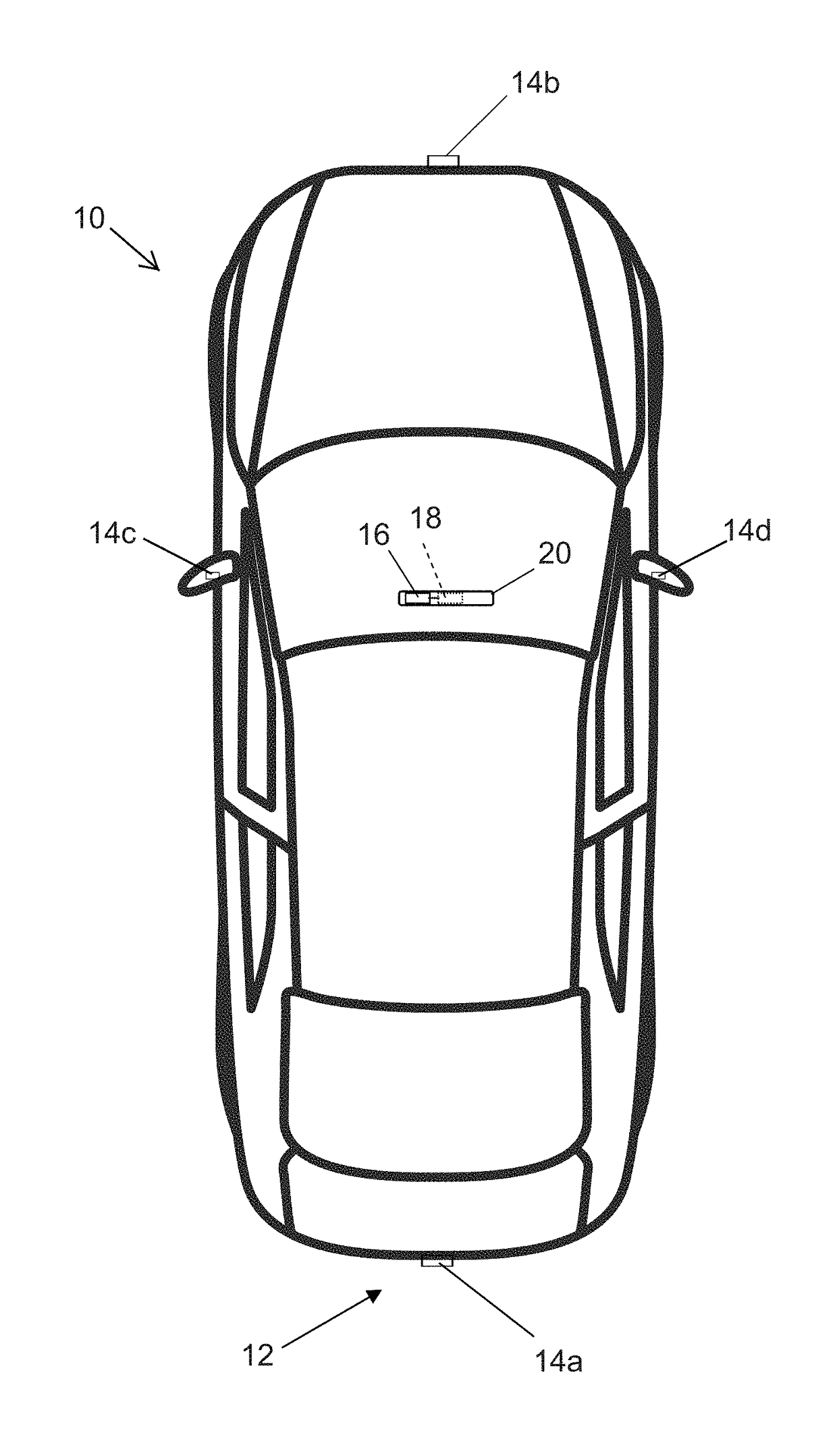
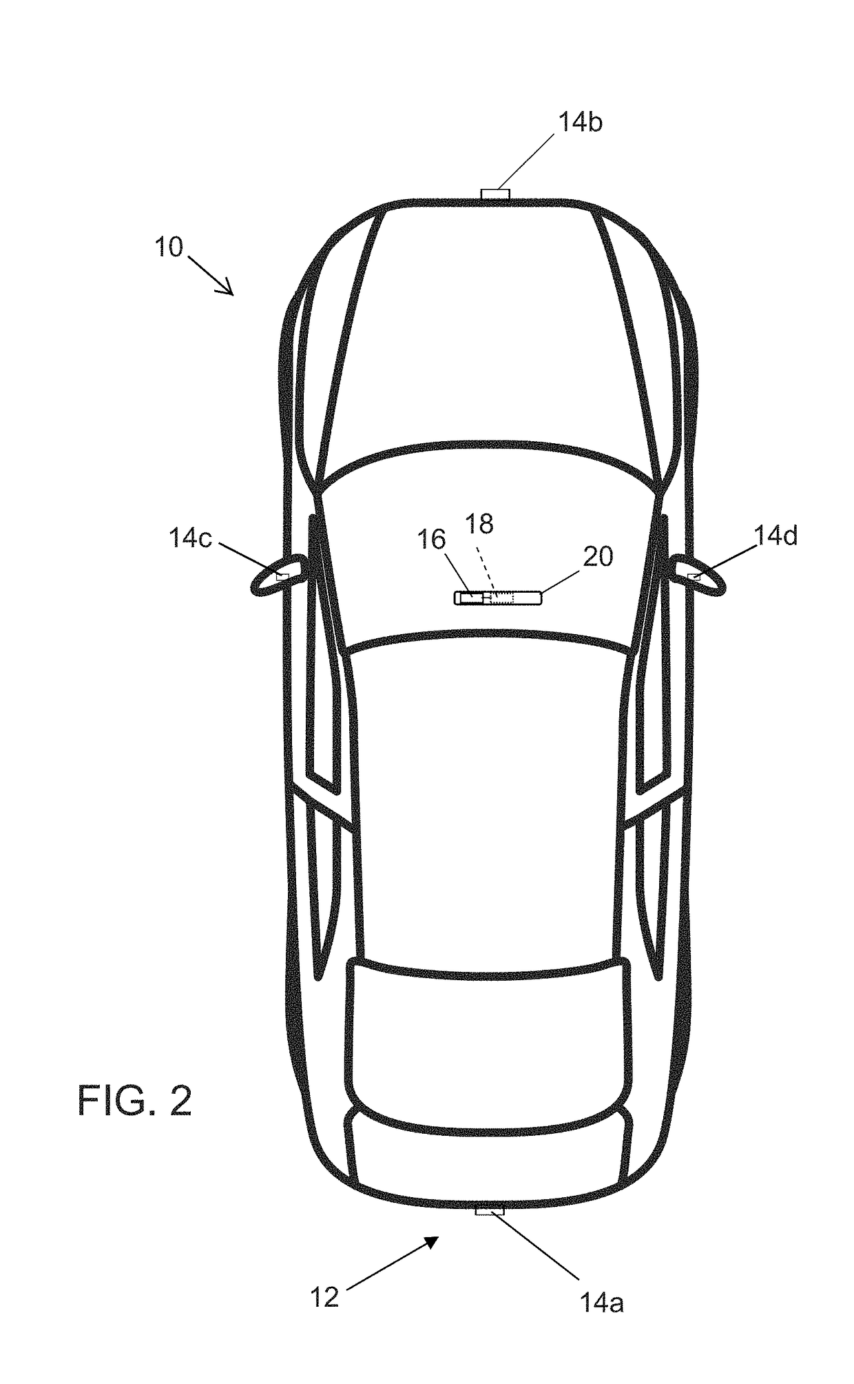
[0020]A vehicle vision system and / or driver assist system and / or object detection system and / or alert system operates to capture images exterior of the vehicle and may process the captured image data to display images and to detect objects at or near the vehicle and in the predicted path of the vehicle, such as to assist a driver of the vehicle in maneuvering the vehicle in a rearward direction. The vision system includes an image processor or image processing system that is operable to receive image data from one or more cameras and provide an output to a display device for displaying images representative of the captured image data. Optionally, the vision system may provide a top down or bird's eye or surround view display and may provide a displayed image that is representative of the subject vehicle, and optionally with the displayed image being customized to at least partially correspond to the actual subject vehicle.

[0021]Referring now to the drawings and the illustrative embo...


PUM


Abstract

A camera for a vision system of a vehicle includes a front housing portion having a lens, a circuit board having circuitry established thereat, and a plastic rear housing portion having a connector for electrically connecting to a connector end of a wire harness of the vehicle when the camera is disposed at the vehicle. The front housing portion is mated with the rear housing portion with the circuit board disposed therein. The rear housing portion includes internal wall structure establishing internal surfaces of the rear housing portion. The connector of the rear housing portion includes a multi-pin connector having terminals for electrically connecting to circuitry at the circuit board. An electrically conductive metallic shield element is formed to be disposed within the rear housing portion and to correspond with the internal surfaces of the rear housing portion.

Description

CROSS REFERENCE TO RELATED APPLICATIONS[0001]The present application claims the filing benefits of U.S. provisional application, Ser. No. 62 / 313,278, filed Mar. 25, 2016, which is hereby incorporated herein by reference in its entirety. The present application also is a continuation-in-part of U.S. patent application Ser. No. 15 / 062,524, filed Mar. 7, 2016 (Attorney Docket MAG04 P-2707), which claims the filing benefits of U.S. provisional applications, Ser. No. 62 / 217,118, filed Sep. 11, 2015; Ser. No. 62 / 204,166, filed Aug. 12, 2015; Ser. No. 62 / 164,619, filed May 21, 2015, Ser. No. 62 / 154,396, filed Apr. 29, 2015, and Ser. No. 62 / 130,130, filed Mar. 9, 2015, which are all hereby incorporated herein by reference in their entireties.FIELD OF THE INVENTION[0002]The present invention relates generally to a vehicle vision system for a vehicle and, more particularly, to a vehicle vision system that utilizes one or more cameras at a vehicle.BACKGROUND OF THE INVENTION[0003]Use of imagin...

Claims


Application Information

Patent Timeline
IPC IPC(8): H04N5/225H01R12/71H01R13/6582H04N7/10
CPCH04N5/2257H04N5/2252H01R13/6582H04N7/10H01R12/716H04N5/2253H01R2103/00H01R9/0518H01R12/714H01R13/2421H01R13/652H01R13/6583H01R13/6594H01R13/6597H01R24/50H01R27/02H01R2101/00H04N7/18H01R2201/26H04N23/51H04N23/57
Inventor CONGER, JONATHAN D.
Owner MAGNA ELECTRONICS
Why Eureka
Try Eureka