Eureka AIR delivers breakthrough ideas for toughest innovation challenges, trusted by R&D personnel around the world.

Endoscope connector, endoscope, and endoscope system

Active Publication Date: 2017-07-20
FUJIFILM CORP
View PDF0 Cites 0 Cited by
  • Summary
  • Abstract
  • Description
  • Claims
  • Application Information

AI Technical Summary

Benefits of technology

The present invention is aimed at providing an endoscope connector with a window glass part that is less likely to collect water droplets and dirt, and can perform stable image communication. The endoscope and endoscope system utilizing this endoscope connector can perform image signal communication without compromising laser efficiency, resulting in high accuracy of image processing.

Problems solved by technology

However, the endoscope device described in Japanese Patent Application Laid-Open No. 2008-93113 relates to a technology for making the connector watertight on the control device side, but does not consider the connector on the endoscope side.
Therefore, it still cannot resolve the problem that the window glass part becomes dirty owing to water droplets or water scale after cleaning and sterilizing the window glass part of the connector on the endoscope side.

Method used


Image

  • Endoscope connector, endoscope, and endoscope system
  • Endoscope connector, endoscope, and endoscope system
  • Endoscope connector, endoscope, and endoscope system

Examples


Embodiment Construction

[0046]Hereinafter, a description is given of an endoscope connector, an endoscope, and an endoscope system according to the present invention with reference to the attached drawings. In the description, the word “to” is used to mean that numerals before and after “to” are included as a lower limit and an upper limit.

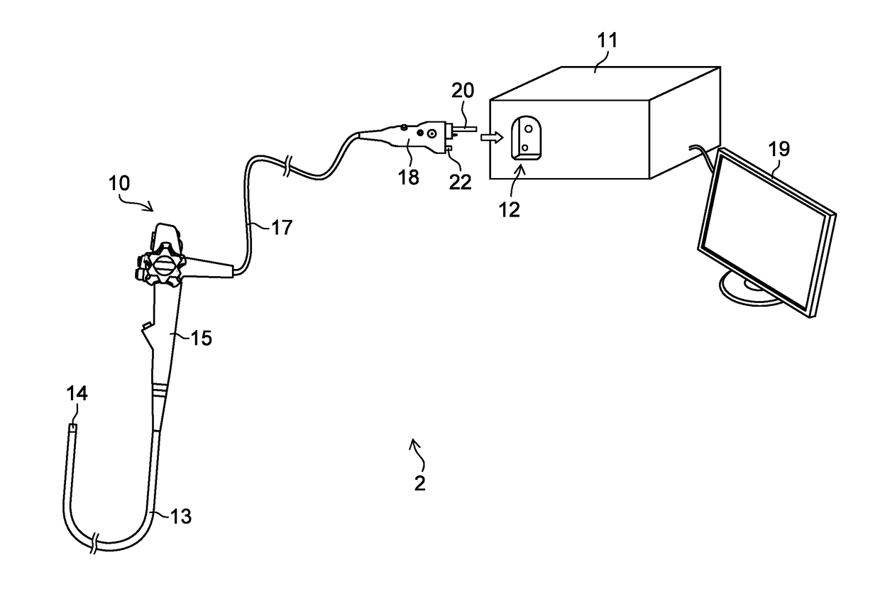
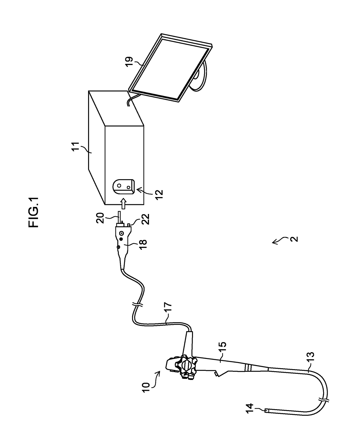
[0047]FIG. 1 is an outer appearance view showing an endoscope system to which the present invention is applied. As shown in FIG. 1, an endoscope system 2 includes an endoscope 10, and an endoscope processor device (processor device for endoscope) 11.

[0048]The endoscope 10, which is illustrated as a flexible scope, has a flexible insertion portion 13 to be inserted in a body cavity of a patient, an operating portion 15 joined to a proximal end part of the insertion portion 13, a universal cord 17 joined to the operating portion 15, and an endoscope connector (connector for endoscope) 18 provided at an end of the universal cord 17 and connected to a processor device connec...


PUM


Abstract

The invention provides an endoscope connector capable of stably performing image communication, an endoscope including the endoscope connector and endoscope system. An endoscope connector is provided in an endoscope having an imaging unit at a distal end of an insertion portion, connected with an endoscope processor device, and provided with an image signal transmitting unit transmitting an image signal with respect to the endoscope processor device via optical communication. The image signal transmitting unit is arranged in an image signal transmitting connector connected with a processor device connector. The image signal transmitting connector includes a glass member provided at the tip end through which the image signal passes and a guide member formed on a circumference of the glass member. The guide member has grooves thereon radially extending from the glass member.

Description

CROSS-REFERENCE TO RELATED APPLICATIONS[0001]The present application claims priority under 35 U.S.C. §119 to Japanese Patent Application No. 2016-008569, filed on Jan. 20, 2016. The above application is hereby expressly incorporated by reference, in its entirety, into the present application.BACKGROUND OF THE INVENTION[0002]Field of the Invention[0003]The present invention relates to an endoscope connector, an endoscope, and an endoscope system, and particularly relates to an endoscope connector, an endoscope, and an endoscope system which transmit signals by way of optical communication.[0004]Description of the Related Art[0005]An endoscope system includes an endoscope and an endoscope processor device. The endoscope includes an imaging unit for taking an image in a body cavity such as a CCD (Charge Coupled Device) image sensor and a connector attached to the endoscope processor device, and the endoscope processor device includes a connector to which the connector of the endoscope ...

Claims


Application Information

Patent Timeline
IPC IPC(8): A61B1/00A61B1/05
CPCA61B1/00126A61B1/05A61B1/00165A61B1/00013A61B1/04A61B1/121A61B1/00124A61B1/126
Inventor HARA, KAZUYOSHIFUKUSHIMA, KIMITAKE
Owner FUJIFILM CORP
Why Eureka
Eureka Blog
Learn More