
Controller for vehicle and control method

a control method and vehicle technology, applied in the direction of couplings, transportation and packaging, road transportation, etc., can solve the problems of increasing the load of the engine, unable to transmit the power of the engine, and the request for travel performance (accelerating performance) cannot be satisfied

Inactive Publication Date: 2017-07-20
TOYOTA JIDOSHA KK
View PDF0 Cites 4 Cited by
  • Summary
  • Abstract
  • Description
  • Claims
  • Application Information

AI Technical Summary

Benefits of technology

The disclosure provides a power transmission apparatus for a vehicle that can transmit power from the engine to the wheels while keeping the engine's speed within a safe range. This is achieved through the execution of slip control by the clutch, which prevents excessive load on the engine and reduces the likelihood of damage to the clutch during the slipping state. Additionally, the patent provides a control method for a vehicle that includes an accelerating operation member, a clutch, a clutch actuator, and an electronic control unit. The control method includes executing coasting control to disengage the clutch for traveling, determining whether the current travel state is suitable for engaging the clutch, and prohibiting the engagement of the clutch when the current travel state is not suitable for engaging the clutch. The execution of slip control is then performed when an acceleration request is made through the operation of the accelerating operation member.

Problems solved by technology

Thus, power of the engine is not transmitted to the drive wheels, and requested travel performance (accelerating performance) cannot be satisfied.
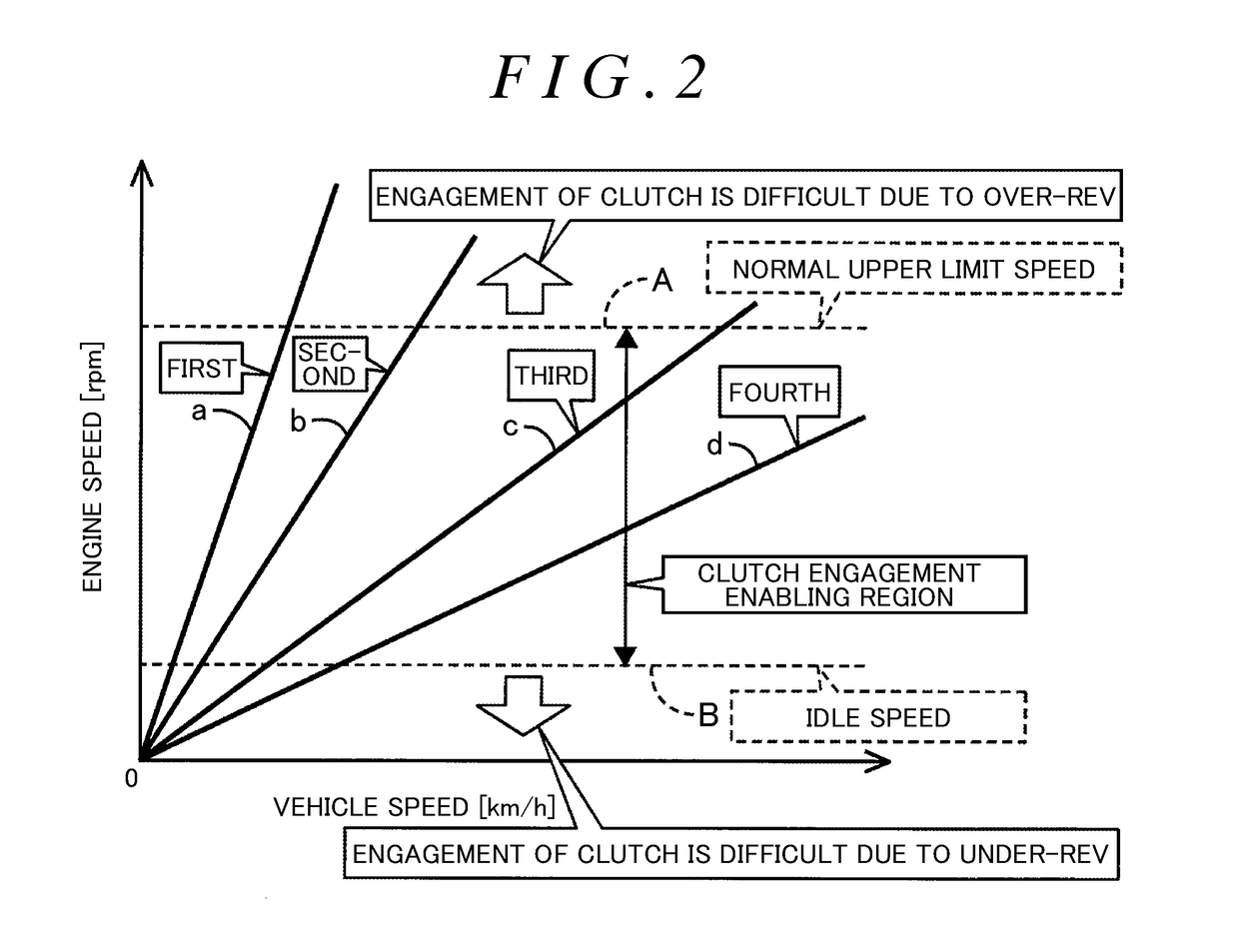
On the contrary, when the accelerating request is prioritized and the clutch is engaged, the over-rev or the under-rev of the engine possibly occurs, which possibly increases a load of the engine.

Method used


Image

  • Controller for vehicle and control method
  • Controller for vehicle and control method
  • Controller for vehicle and control method

Examples


Embodiment Construction

[0024]A detailed description will hereinafter be made on an embodiment of the disclosure with reference to the drawings.

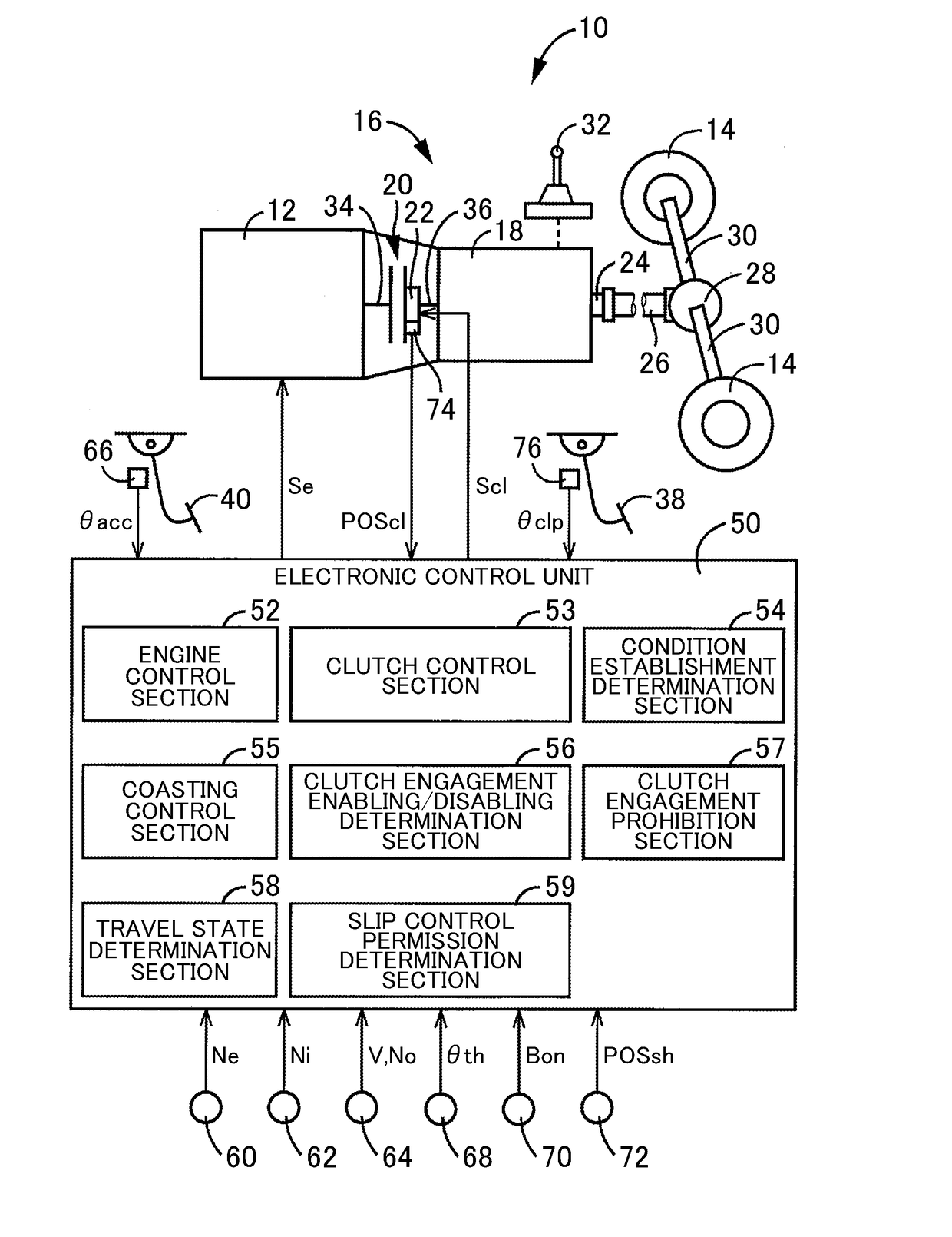
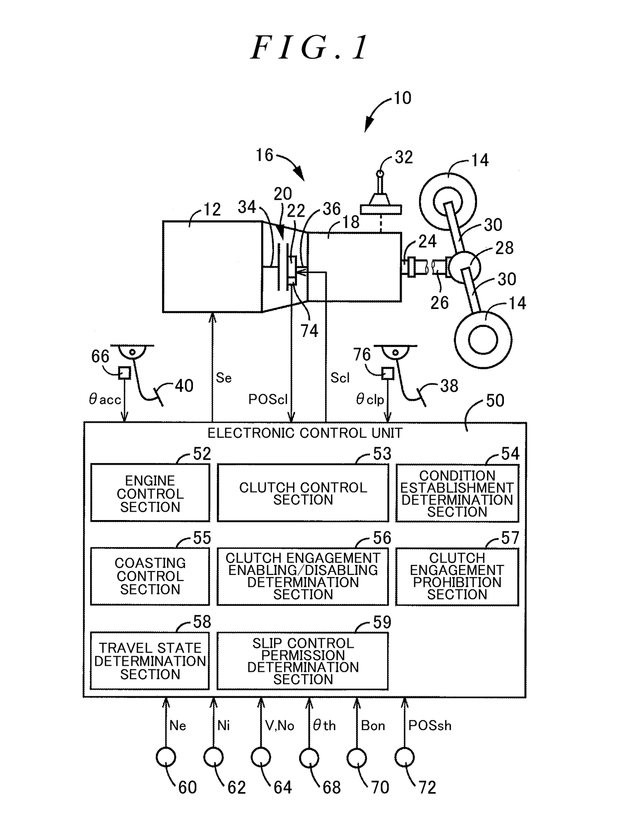
[0025]FIG. 1 is a view for explaining a schematic configuration of a vehicle 10, to which the disclosure is applied, and is also a view for explaining main sections of a control system for various types of control in the vehicle 10. In FIG. 1, the vehicle 10 includes an engine 12, drive wheels 14, and a power transmission apparatus 16 for a vehicle (hereinafter referred to as a power transmission apparatus 16) that is provided in a power transmission route between the engine 12 and the drive wheels 14. The power transmission apparatus 16 includes: a transmission 18 for constituting a part of the power transmission route between the engine 12 and the drive wheels 14; a clutch 20 for connecting / disconnecting the power transmission route between the engine 12 and the transmission 18; a clutch actuator 22 for switching among engagement, slipping, and disengagement of t...


PUM


Abstract

A controller including an electronic control unit, the electronic control unit executes slip control of a clutch when a specified termination condition is established during execution of coasting control and an acceleration request is made through an operation of an accelerating operation member even when engagement of the clutch is prohibited. Thus, power from an engine can be transmitted to drive wheels while a load imposed on the engine is suppressed.

Description

INCORPORATION BY REFERENCE[0001]The disclosure of Japanese Patent Application No. 2016-009182 filed on Jan. 20, 2016 including the specification, drawings and abstract is incorporated herein by reference in its entirety.BACKGROUND[0002]1. Technical Field[0003]The disclosure relates to a controller for a vehicle and control method, the vehicle including: a transmission capable of switching a gear stage by a manual operation; a clutch for connecting / disconnecting a power transmission route between an engine and the transmission; and a clutch actuator for switching among engagement, slipping, and disengagement of the clutch.[0004]2. Description of Related Art[0005]In a power transmission apparatus for a vehicle that includes: a transmission for constituting a part of a power transmission route between an engine and drive wheels and capable of switching a gear stage by a manual operation; a clutch for connecting / disconnecting the power transmission route between the engine and the trans...

Claims


Application Information

Patent Timeline
Patent Type & Authority Applications(United States)
IPC IPC(8): F16D48/06F16H63/46
CPCF16D48/06F16H63/46B60Y2300/18083F16D2500/102F16D2500/10412F16D2500/5085F16D2500/30806F16D2500/3067F16D2500/3166F16D2500/30406F16D2500/1045B60W10/02B60W10/11B60W30/18072B60W2030/18081B60W2710/025B60W2520/10B60W2510/0647F16D2500/3144F16D2500/50858F16D2500/70426Y02T10/60F16D1/00
Inventor OKUBO, TADANAO
Owner TOYOTA JIDOSHA KK
Learn More