Pattern inspection apparatus

a technology of pattern image and inspection apparatus, which is applied in the field of pattern image inspection apparatus, can solve the problems of displacement of pattern image on imaging sensor, long optical path, and imaging system susceptible to air fluctuation influence,

Active Publication Date: 2017-07-20
NUFLARE TECH INC
View PDF2 Cites 10 Cited by
  • Summary
  • Abstract
  • Description
  • Claims
  • Application Information

AI Technical Summary

Problems solved by technology

One of main factors for degradation of yield may be pattern defects in a mask used in transferring an ultrafine pattern to a semiconductor wafer by exposure of a photolithography technique.
Thus, lenses having long focal distance have to be combined, necessarily resulting in a long optical path.
Therefore, the imaging system is susceptible to the influence of air fluctuation.
This results in displacement of a pattern image on an imaging sensor.
This displacement causes an error when the pattern image is compared with a reference image, and thus is a factor for preventing highly accurate inspection.

Method used


Image

  • Pattern inspection apparatus
  • Pattern inspection apparatus
  • Pattern inspection apparatus

Examples


first embodiment

[0027]Hereinafter, in a first embodiment, a pattern inspection apparatus capable of obtaining displacement due to influence of air fluctuation on an optical image for inspection is described.

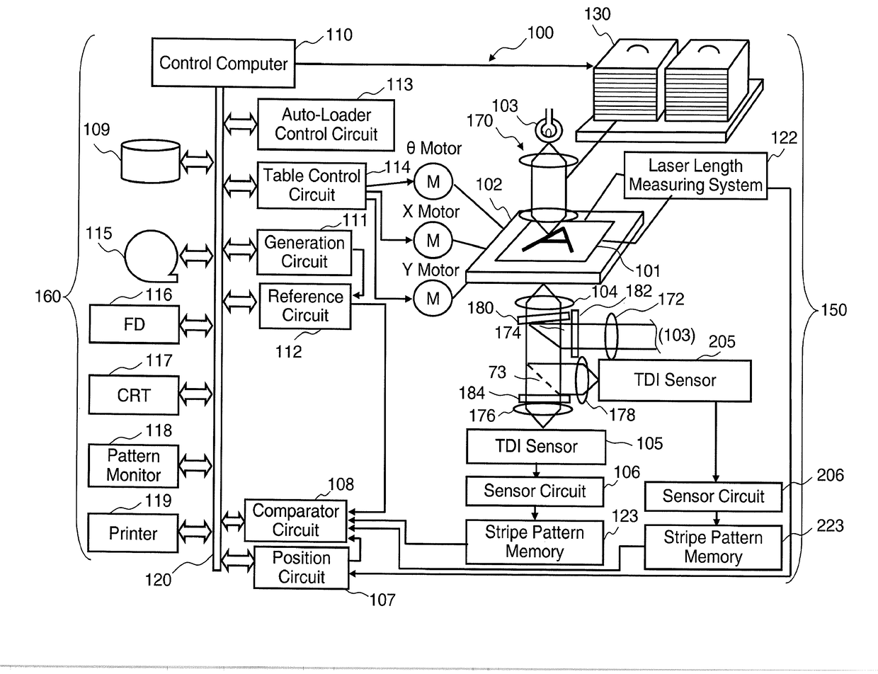
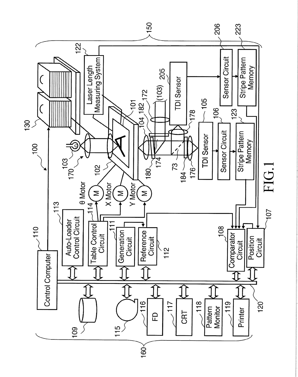
[0028]FIG. 1 is a configuration diagram illustrating a pattern inspection apparatus according to the first embodiment. In FIG. 1, an inspection apparatus 100 that inspects defects in a pattern formed on a mask substrate 101 (an example inspection object substrate) includes an optical image acquisition unit 150 and a control system circuit 160 (controlling unit).

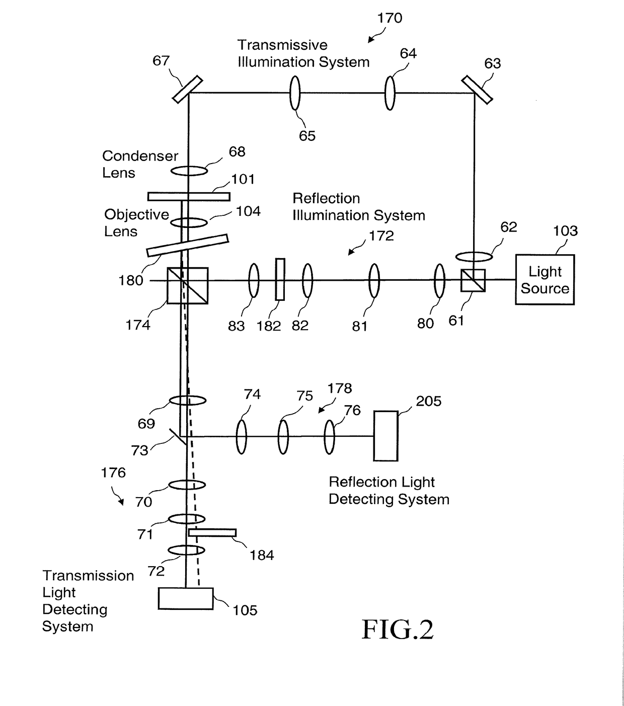
[0029]The optical image acquisition unit 150 includes a light source 103, a transmissive illumination optical system 170, an XYθ table 102 disposed movably, an objective lens 104, a semi-transmission reflection plate 180, a beam splitter 174, a reflection illumination optical system 172, an imaging optical system 176, a mirror 73, an imaging optical system 178, diaphragms 182 and 184, time delay integration (TDI) sensors 105 and 205 (exam...


PUM

PropertyMeasurementUnit
reflectanceaaaaaaaaaa
transmittanceaaaaaaaaaa

Abstract

According to one aspect of the present invention, a pattern inspection apparatus includes a first diaphragm that is positioned on an optical path of a reflection illumination optical system and has a first reference pattern of a line-and-space pattern formed thereon; a semi-transmission reflection plate configured to reflect a portion of a reference pattern image that has passed through the first reference pattern; a second diaphragm which is positioned on an optical path of the imaging optical system, on which the portion of the reference pattern image reflected by the semi-transmission reflection plate is projected, and which has a second reference pattern of a line-and-space pattern formed thereon; and a first time delay integration sensor (TDI sensor) configured to receive the portion of the reference pattern image that has passed through the second reference pattern.

Description

CROSS-REFERENCE TO RELATED APPLICATION[0001]This application is based upon and claims the benefit of priority from prior Japanese Patent Application No. 2016-007206 filed on Jan. 18, 2016 in Japan, the entire contents of which are incorporated herein by reference.BACKGROUND OF THE INVENTION[0002]Field of the Invention[0003]Embodiments described herein relate generally to a pattern inspection apparatus. Embodiments described herein relate, for example, to a pattern inspection technique for inspecting pattern defects in an object to be a target object used to manufacture a semiconductor, and to an inspection apparatus that inspects an exposure mask substrate used in manufacturing a semiconductor element and a liquid crystal display (LCD).[0004]Related Art[0005]In recent years, the circuit line width required for semiconductor elements is getting even smaller due to increasing integration level and increasing capacity of a large-scale integrated circuit (LSI). These semiconductor eleme...

Claims


Application Information

Patent Timeline
Patent Type & Authority Applications(United States)
IPC IPC(8): G06K9/62G06T7/73G03F7/20H04N5/235G06T7/00G01N21/956H04N5/225H04N5/372G06V10/147
CPCG06K9/6203H04N5/2256G06T7/74H04N5/372H04N5/2351G01N2021/95676G06T7/001G01N21/95607G03F7/702G06T2207/30148H04N5/2258G03F1/84G06V10/147G06V10/7515H04N23/56H04N25/768H04N25/71G03F7/70141G03F7/70275G03F7/70483G03F7/70833H04N23/45H04N23/71
Inventor OGAWA, RIKI
Owner NUFLARE TECH INC
Why Eureka
Try Eureka