Method for determining the remaining life of a thermal mass in a shipping package while in transit

a technology of thermal mass and thermal mass, which is applied in the direction of domestic cooling devices, navigation instruments, instruments, etc., can solve the problems of high cost, uncertainty, high risk, and high risk of shippers, and achieves significant risk and higher cost of shipping commodities into those markets. , the effect of increasing the risk of shipping

Inactive Publication Date: 2017-07-20
KLATU NETWORKS
View PDF7 Cites 14 Cited by
  • Summary
  • Abstract
  • Description
  • Claims
  • Application Information

AI Technical Summary

Benefits of technology

[0013]According to an aspect of the description, the at least one bladder conformed to the inner surface of the inner chamber may have a shape adapted to provide protection of the Thermal Source and the one or more commodities or other materials.

Problems solved by technology

The transport of temperature-stabilized commodities such as research specimens and pharmaceuticals and other biologics (“commodities”) exposes the shipper to risk, uncertainty and high costs particularly when international shipping is involved.
When a shipping package or container is in the hands of a shipping company, the shipper cannot easily determine the location and status of the shipment with respect to a planned delivery date, whether the commodities in the shipping package have been exposed to excessive temperatures, shock, vibration or tilt, and most importantly, whether cold-source commodities contained within the package such as dry-ice or liquid nitrogen (“Thermal Source”), have an adequate charge remaining to last for the expected (or unexpected) duration of the shipment.
However, shipping commodities into those markets involves significantly greater risk and higher cost due to longer shipping times, prolonged exposure to shock and vibration and greater potential that the Thermal Source will be dissipated before the shipment is completed.
Today, the cost of developing a new drug averages $800 million.

Method used


Image

  • Method for determining the remaining life of a thermal mass in a shipping package while in transit
  • Method for determining the remaining life of a thermal mass in a shipping package while in transit
  • Method for determining the remaining life of a thermal mass in a shipping package while in transit

Examples


Embodiment Construction

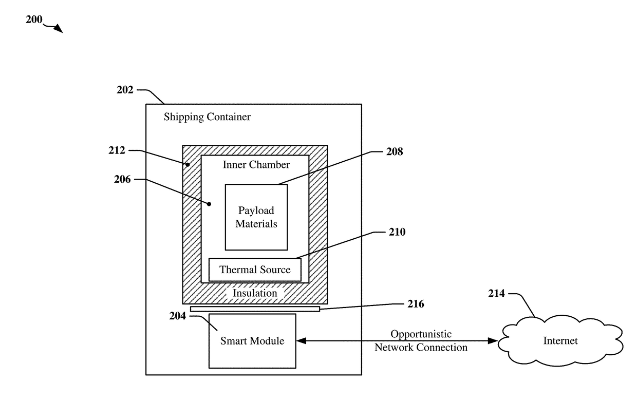
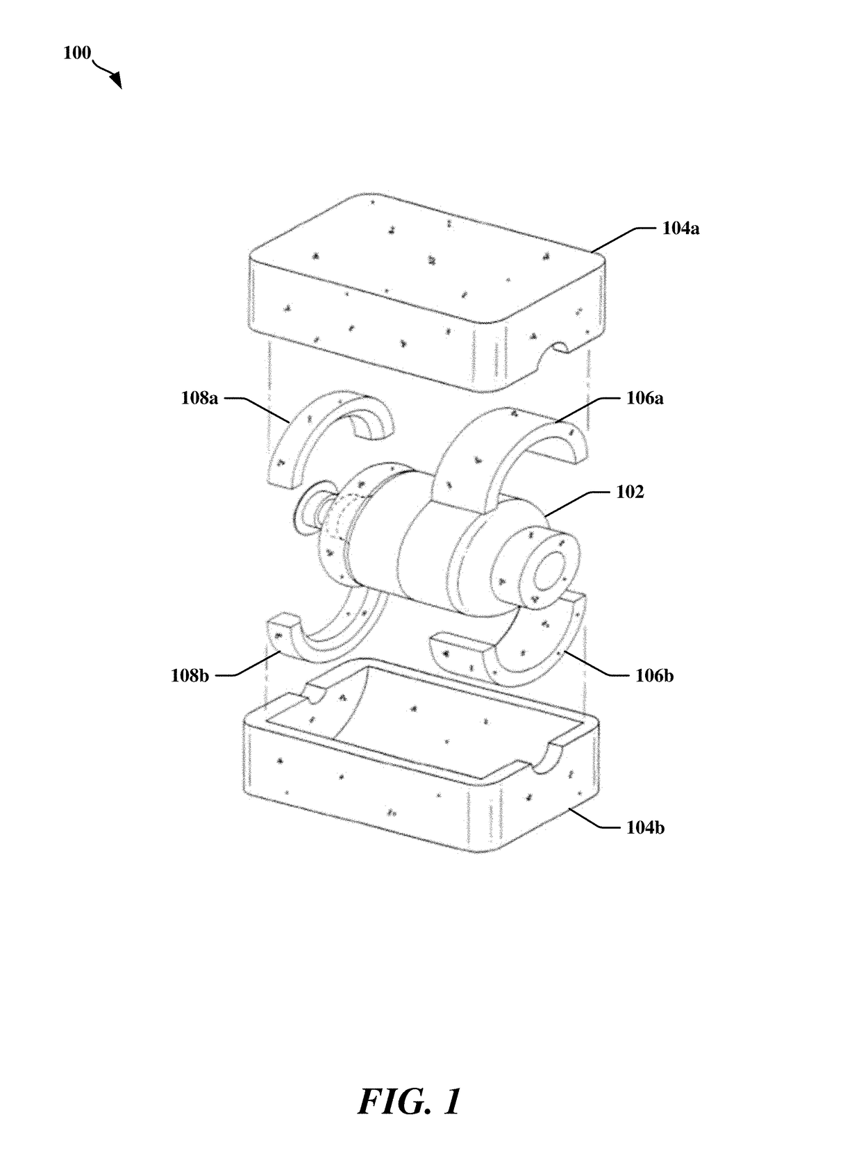
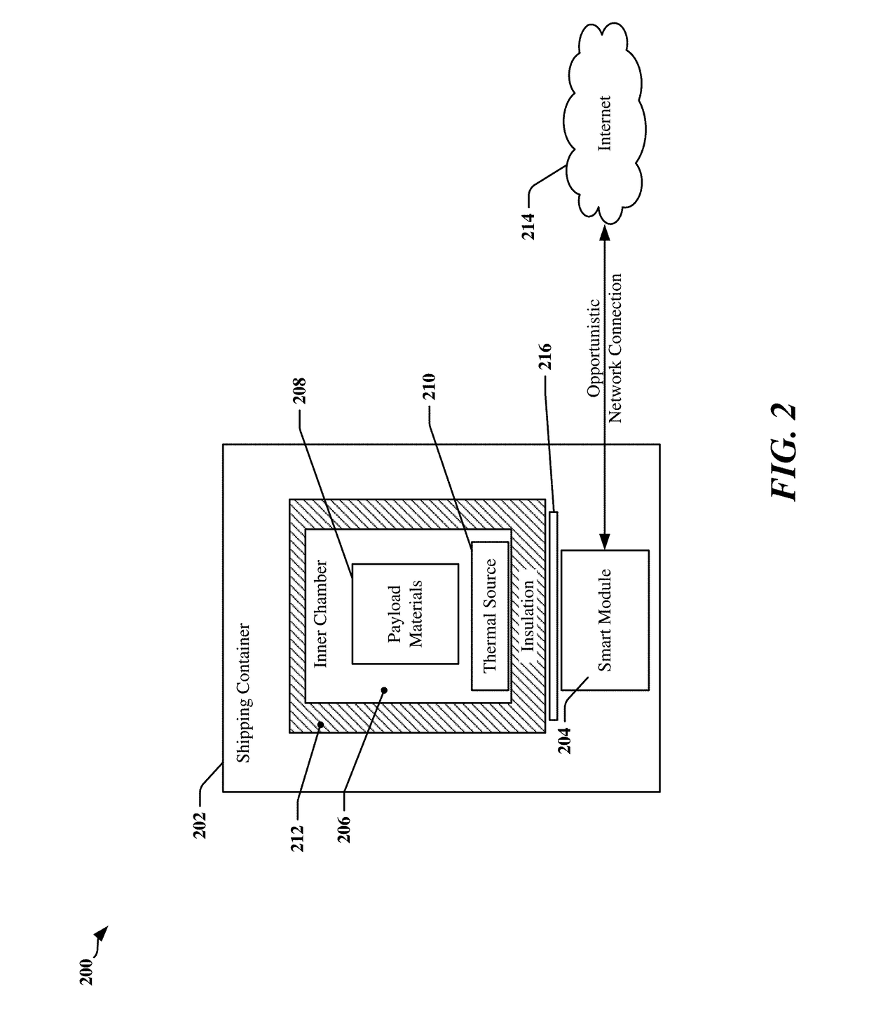
[0024]Embodiments of the present invention will now be described in detail with reference to the drawings, which are provided as illustrative examples so as to enable those skilled in the art to practice the invention. Notably, the figures and examples below are not meant to limit the scope of the present invention to a single embodiment, but other embodiments are possible by way of interchange of some or all of the described or illustrated elements. Wherever convenient, the same reference numbers will be used throughout the drawings to refer to same or like parts. Where certain elements of these embodiments can be partially or fully implemented using known components, only those portions of such known components that are necessary for an understanding of the present invention will be described, and detailed descriptions of other portions of such known components will be omitted so as not to obscure the invention. In the present specification, an embodiment showing a singular compon...


PUM


Abstract

A shipping container is described for use with methods for monitoring and controlling shipment of a temperature controlled material and determining the remaining useful life of a Thermal Source contained within the shipping container. The container comprises an inner enclosure adapted to carry one or more commodities during shipment, a bladder conformed to the inner surface of the inner chamber, or a plate upon which commodities are place, and instrumented with at least one transducer and at least one processing device configured to receive measurements from the at least one transducer. The processing device communicates the measurements to a networked device upon detecting the presence of a network. The networked device may transmit commands to the processing device that causes the processing device to adjust a configuration parameter.

Description

CLAIM OF PRIORITY UNDER 35 U.S.C. §119[0001]The present application for patent is a continuation-in-part of U.S. patent application Ser. No. 12 / 852,413 filed Aug. 6, 2010, which is a continuation of U.S. patent application Ser. No. 12 / 658,641 filed Feb. 4, 2010, which claimed priority from U.S. Provisional Patent Application No. 61 / 150,271 filed Feb. 5, 2009, and the present application for patent is a continuation-in-part of U.S. patent application Ser. No. 13 / 781,698 filed Feb. 28, 2013, which claimed priority to Provisional Application No. 61 / 604,336 filed Feb. 28, 2012, and each of these applications is hereby expressly incorporated by reference herein.FIELD OF THE INVENTION[0002]The present invention is in the field of methods for monitoring and controlling shipment of a temperature controlled material.BACKGROUND OF THE INVENTION[0003]The transport of temperature-stabilized commodities such as research specimens and pharmaceuticals and other biologics (“commodities”) exposes th...

Claims


Application Information

Patent Timeline
Patent Type & Authority Applications(United States)
IPC IPC(8): G06Q10/08G01C21/00G01G5/00
CPCG06Q10/0832G01C21/005G01G5/003F25D3/105F25D3/125F25D29/001G01G19/414
Inventor KRISS, RICHARD
Owner KLATU NETWORKS
Why Eureka
Try Eureka