
Connector housing with heat dissipation structure

a technology of heat dissipation structure and connection housing, which is applied in the direction of coupling device connection, instrument, fibre light guide, etc., can solve the problems of reducing easy damage, and easy detachment of locking members, so as to increase the heat dissipation area of the heat dissipation unit, the effect of enhancing the emi shielding effect and reducing the opening of the top pla

Active Publication Date: 2017-07-27
NEXTRONICS ENG CORP
View PDF5 Cites 15 Cited by
  • Summary
  • Abstract
  • Description
  • Claims
  • Application Information

AI Technical Summary

Benefits of technology

This patent describes a connector housing with a heat dissipation structure. The design reduces the area of the housing's top plate, improving EMI shielding. The holding member is secure and can withstand external force. The heat dissipation area is increased because the holding member engages with the top plate and side arm penetrates through the interior space of the heat dissipation unit. The holding member is not easily released and has a U-shaped cross section, increasing its strength. The heat dissipation unit includes a spring that provides a reliable heat dissipation effect and can be modified according to the housing's height. The heat dissipation unit has a division plate that allows multiple units to be integrated as one body and increases the heat dissipation area. The overall design improves the connector's performance and stability.

Problems solved by technology

However, the traditional heat dissipation unit engages with an opening of the connector housing by the locking member, and the EMI shielding effects is decreased due to the opening.
Moreover, the structure strength of the traditional locking member is weak, so the locking member is detached and damages easily.

Method used


Image

  • Connector housing with heat dissipation structure
  • Connector housing with heat dissipation structure
  • Connector housing with heat dissipation structure

Examples


first embodiment

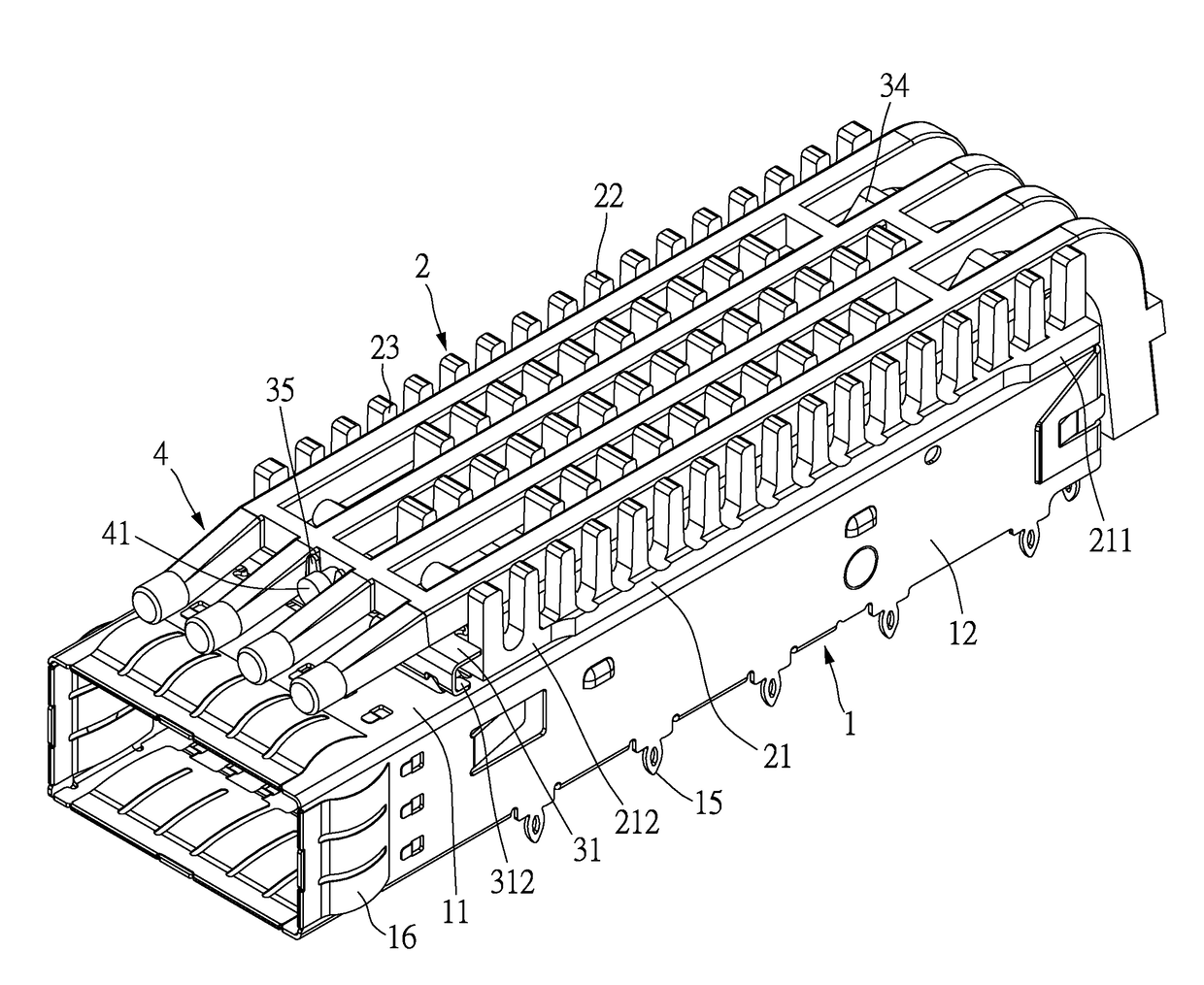
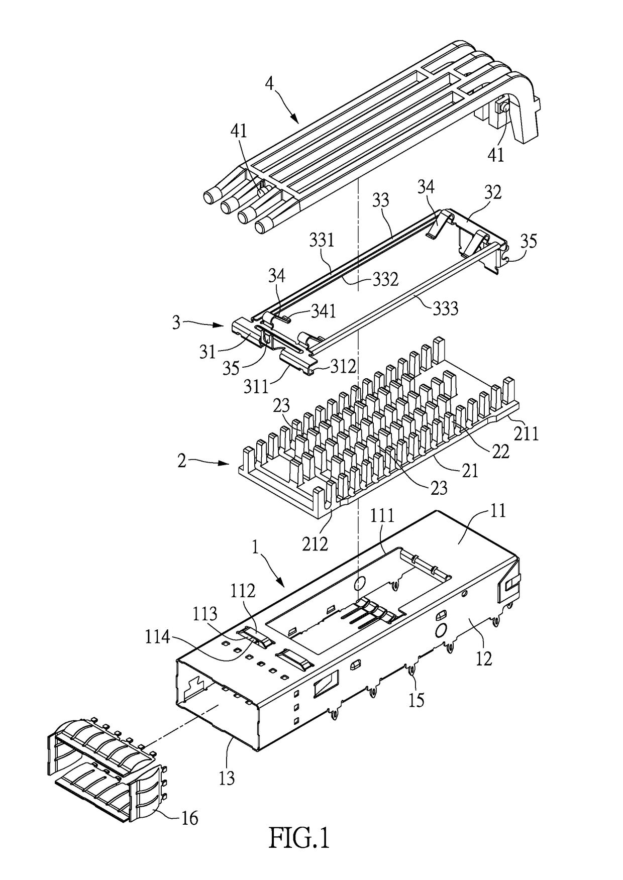
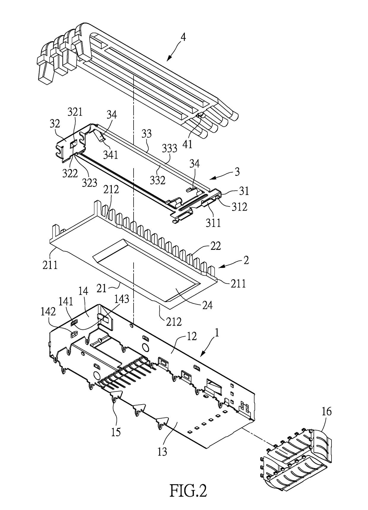
[0027]Please refer to FIGS. 1 and 2. The instant disclosure provides a connector housing with heat dissipation structure meeting the Quad Small Form-factor pluggable transceiver module specification, and may be, but not limited to, available in 1×1, 1×2, 1×3, 1×4, 1×5, and 1×6 configurations. The connector housing with heat dissipation structure of the present invention includes a housing 1, a heat dissipation unit 2, and a holding member 3. The width of the housing 1 is varied and can be modified as needed, such as 1×1˜1×6 configurations. Similarly, the number of the heat dissipation unit 2 and the holding member 3 may be one, or more than one. In this embodiment, the connector housing is with 1×1 configuration, and the number of the housing 1, the heat dissipation unit 2, and the holding member is one.

[0028]The housing 1 is made of metal, includes a top plate 11, two side walls 12, a bottom plate 13, and a back cover 14. The top plate 11, the two side walls 12, the bottom plate 13...

second embodiment

[0039]Please refer to FIGS. 8 and 9. The inner space of the housing 1 is disposed with at least one division plate 17, the division plate 17 is parallel to the two side walls 12 to divide the inner space of the housing 1 into at least two parts, and at least two heat dissipation units 2 and at least two holding members 3 are arranged accordingly. In this embodiment, a 1×4 configuration is described as follows. The width of the housing 1 is increased, and is about four times that of the 1×1 configuration in the first embodiment, and four heat dissipation units 2 and four holding members 3 are arranged accordingly. In this embodiment, three division plates 17 are arranged, and the number of the division plates 17 may be, but is not limited to, one, two, four, or five. The number of the orifice 111 of the housing 1, the fasten piece 112, the opening 113, the convex hull 141, the stop part 142, the pin 15, and the ground spring 16 are increased as required to set up the heat dissipation...


PUM


Abstract

A connector housing with heat dissipation structure includes a housing, a heat dissipation unit and a holding member. A first end part of the holding member is fixed to a top plate of the housing by using a first tongue piece engaged with a fastening piece, so an area of an opening of top plate is decreased and the EMI shielding effect is better. Two side arms of the holding member pass through the trenches inside the heat dissipation unit, such that the width of the heat dissipation unit is not limited and a heat dissipation area can be increased. The second end part of the holding member includes a second tongue piece plugged into a convex hull at a back cover, and an arrival end of the second end part withstands a stop part, so the holding member is not released easily and can endure an external force.

Description

BACKGROUND[0001]1. Technical Field[0002]The present disclosure is related to a connector housing with heat dissipation structure, and more particularly, to a connector housing with heat dissipation structure adapted to a Quad Small Form-factor Pluggable Plus.[0003]2. Description of Related Art[0004]Transceivers are utilized to interconnect circuit cards of communication links and other electronic modules or assemblies. Various international and industry standards define the type of connectors used to connect computers to external communication devices, such as modems, network connectors, and other transceivers. A well-known type of transceiver module developed by an industry consortium and known as a Gigabit Connector Converter (GBIC) provides a connection between a computer and an Ethernet, Fiber Channel, or another data communication environment.[0005]It is desirable to miniaturize transceivers in order to increase the port density at a network connection (at switch boxes, cabling...

Claims


Application Information

Patent Timeline
Patent Type & Authority Applications(United States)
IPC IPC(8): H01R13/502H01R13/6583H01R13/717
CPCH01R13/502H01R13/6583H01R13/7172G02B6/0008G02B6/4269G02B6/4277G02B6/4284G02B6/42
Inventor SU, HOU-ANZENG, DING YONG
Owner NEXTRONICS ENG CORP
Learn More