Battery management

a battery and management technology, applied in the direction of safety/protection battery circuits, electric vehicles, charging equalisation circuits, etc., can solve the problems of increasing the risk of exceeding the cell voltage limit on a few cells, the majority of unconnected, and so as to reduce the set of connections, reduce the risk of arcing, and reduce the risk of further loosening the connection

Active Publication Date: 2017-07-27
INTERCALUK LTD
View PDF5 Cites 38 Cited by
  • Summary
  • Abstract
  • Description
  • Claims
  • Application Information

AI Technical Summary

Benefits of technology

[0094]The temperature sensors may be connected to the battery monitor by a respective wire. Whilst this may involve a number of wires, it provides a simple way of connecting the sensors whilst electrically isolating the sensor wires from the main electrical system. The wiring is all low voltage unlike voltage monitoring or active balancing connections, thus reducing shock hazard and risk of arcing.
[0095]The temperature sensors may instead be connected to a common communication bus for communicating with said battery monitor. This allows a reduced set of connections with a single bus cable passing from one sensor to the next rather than a dedicated connection from each sensor to the main monitoring point.
[0096]The temperature sensors may communicate wirelessly with the battery monitor. In this arrangement, the sensors are preferably powered by received electromagnetic radiation. This is similar to passive RFID tags where the RF radiation is used energise the temperature sensor which can provide a temperature reading in a returned RF signal. This is advantageous in that no wires are needed to connect them reducing further any issues with loose connections etc.
[0097]Preferably, each temperature sensor has a unique identifier which is communicated to said battery monitor with the temperature information signals. This allows the monitor to identify the specific sensor and potentially adapt its behaviour based on the sensor position. For example, if the monitor knows that a sensor on a cell is in the middle of the battery then higher temperatures may be expected and acceptable patterns may be adjusted accordingly. Equally sensors on the outside of the battery may be susceptible to external factors such as ambient temperature.
[0098]The battery monitor may be arranged to raise an exception if it does not receive temperature information from all of the temperature sensors. In this way, if a temperature sensor fails for whatever reason, the system can respond in a fail safe manner. However, a limited number of sensors failing to respond may be accommodated. For example, some sensors may have a degree of redundancy such as by providing multiple sensors on each cell.

Problems solved by technology

Whilst connections to cells may still be provided, these can be left unconnected most of the time and only used for occasional monitoring or servicing.
As mentioned above, variations in cells and their response when close to full charge varies, which can lead to differential charging of the cells.
If charging is continued to close to full capacity (e.g. charging until charging current falls to 5 or 10% of initial charge current), as is typical for existing charging arrangements, the risk of exceeding cell voltage limits on a few cells is increased.
Cells with soft shorts will lose charge, potentially only at a very low rate, but this will bring them out of balance with the other cells in the battery.

Method used


Image

  • Battery management
  • Battery management
  • Battery management

Examples


Embodiment Construction

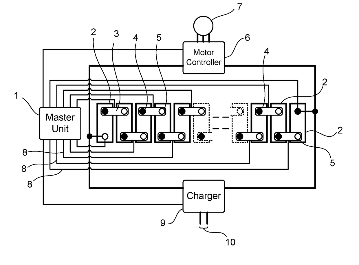
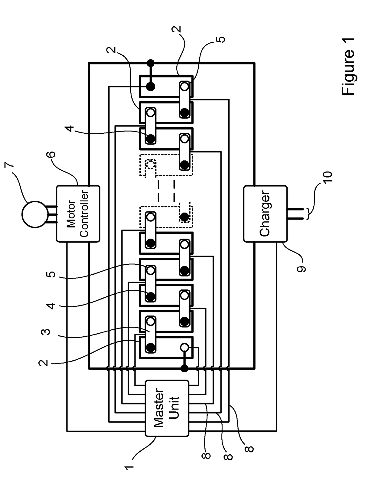
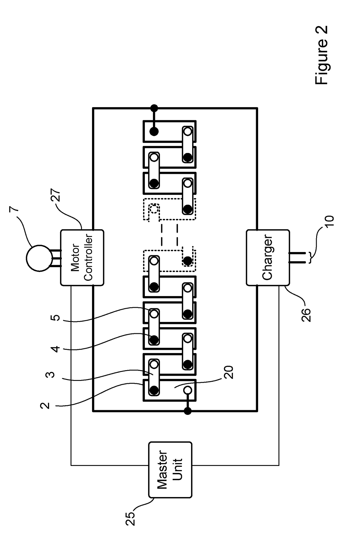
[0143]FIG. 2 shows a rechargeable battery-based system with a plurality of cells 2 arranged in series with each other to form a battery. The cells 2 shown in FIG. 2 may represent either a single cell or a number of cells arranged in a cell module, usually with each of the cells arranged in parallel. Although not essential, the cells in this arrangement are bottom balanced prior to deployment. In this way, the cells will all be charged from a common charge level so that when they are discharged they will all discharge towards this initial bottom balanced level of charge, so that no one cell will be discharged beyond any other, avoiding the possibility of damaging one or more cells.

[0144]The end terminals of the battery are connected to a load which in this case is a motor controller 27 for controlling a motor 7. The motor controller and motor provide a load into which the battery is discharged in use. A charger 26 provides charge to the battery in order to recharge the battery as it ...


PUM


Abstract

The invention provides a method and apparatus for managing a battery comprising a plurality of series connected cells. The battery comprises a plurality of series connected statically balanced cells. The battery is arranged so that a substantially identical load is imposed on all of the cells, in use in order to maintain the balance. A battery charging controller is used for controlling the charging of the battery as is arranged to terminate charging prior to the cells reaching their maximum state of charge. The invention also provides a modified charging regime which controls individual cell voltage to avoid any single cell exceeding a desired voltage.

Description

CROSS-REFERENCE TO RELATED APPLICATIONS[0001]The present application claims priority to PCT International Application No. PCT / GB2015 / 051913 filed on Jun. 30, 2015, which claims priority to UK Patent Application No. 1412636.1 filed Jul. 16, 2014 and UK Patent Application No. 1506337.3 filed Apr. 14, 2015, the entirety of the disclosures of which are expressly incorporated herein by reference.STATEMENT RE: FEDERALLY SPONSORED RESEARCH / DEVELOPMENT[0002]Not ApplicableFIELD OF THE INVENTION[0003]This invention relates to managing charge and discharge of batteries, in particular batteries comprising long series strings of cells.BACKGROUND TO THE INVENTION[0004]Battery Management Systems (“BMS”) are typically used for the control of charging and discharging of a battery or batteries in a battery power source system. The BMS typically manages the operation of such systems but can also provide important fail safety actions to prevent potentially hazardous consequences should a fault occur.[0...

Claims


Application Information

Patent Timeline
Patent Type & Authority Applications(United States)
IPC IPC(8): H02J7/00B60L11/18
CPCH02J7/0026B60L11/1866H02J7/007H02J7/0086H02J7/0013H02J7/0018B60L58/22Y02T10/70Y02E60/10H02J7/007182H02J7/0091H02J7/00H01M10/482H02J7/0014H02J7/00309H02J7/00712
Inventor HARDY, JOHN
Owner INTERCALUK LTD
Why Eureka
Try Eureka