
Heart valve anchoring device

a heart valve and anchoring technology, applied in the field of anchoring devices for heart valves, can solve the problems of abnormal blood leakage, difficult design and size of prosthetic heart valves having the ability to conform to heart annulus, and additional problems for patients, and achieve the effect of stable cross-section and high stiffness

Active Publication Date: 2017-08-03
TRICARES SAS
View PDF5 Cites 6 Cited by
  • Summary
  • Abstract
  • Description
  • Claims
  • Application Information

AI Technical Summary

Benefits of technology

The invention is an anchoring system for a prosthetic heart valve support. The system has two parts - the support and the anchoring device. The support is stiffer than the anchoring device, which helps it fit closely to the heart wall around the native heart valve during each cardiac cycle and ensures proper functioning of the prosthetic heart valve. In simple terms, the system helps to stabilize the prosthetic heart valve and keep it in place.

Problems solved by technology

Mitral regurgitation—the mitral leaflets do not close properly leading to abnormal leaking of blood—is the most commonly occurring valve abnormality.
However, in many repair and replacement procedures, the durability of the devices, or the improper sizing of annuloplasty rings or replacement heart valves, may result in additional issues for the patients.
However, human anatomical variability makes it difficult to design and size a prosthetic heart valve having the ability to conform to a heart annulus.
Especially percutaneous atrioventricular valve replacement is a real challenge as the native atrioventricular valves annuli have a non-circular, non-planar, saddle-like geometry often lacking symmetry.
Current devices developed for percutaneous heart valve replacement were found unsuitable for the following reasons:Firstly, many of these existing devices support the prosthetic heart valve while contacting the annulus; thereby directly transferring to the prosthetic heart valve many of the distorting forces exerted by the surrounding tissue and blood as the heart contracts during each cardiac cycle.
As cardiac replacement devices further comprise heart valves which require a substantially symmetric, cylindrical support around the prosthetic heart valve for proper opening and closing of the leaflets over years of life, when these devices are subjects to movement and forces from the annulus and other surrounding tissues, the prostheses may be compressed and / or distorted, causing the prosthetic leaflets to malfunction.
This stent is designed as a single wall structure with a circular section and does not address the issue of geometrical unpredictability.
Such device does not really prevent paravalvular leakage.
Indeed, as the supporting tissue does not offer a stable circular section, junction between the stent and the native heart valve is not achieved on the entire periphery of the heart valve.
Moreover, with a single wall structure the stent does not mechanically isolate the prosthetic heart valve from the surrounding native tissues, thereby preventing proper functioning of the prosthetic heart valve during each cardiac cycle.Secondly, common stents provide radial anchorage and may migrate or slip relative to the heart wall due to blood flow, movements and forces from the annulus and other surrounding tissues.
However, this circular device is inflexible and the seal between the anchoring device and the native heart valve and surrounding tissues is hard to achieve.
Therefore radial anchorage of a stent designed for aortic valve may be insufficient when used for atrioventricular valve replacement.Thirdly, minimally invasive procedure, without direct vision of the surgical site, strongly relies on cardiac surgeon's skills.
Misalignment of the anchoring device may indeed lead to leakage and unsealing of the device.
However, WO 2006 / 128185 does not disclose a double-wall device at the height of the prosthetic heart valve, but only at the two ends.
Furthermore, the shape of the mushroom-like ends do not closely fits the native surrounding tissue along their entire length.

Method used


Image

  • Heart valve anchoring device
  • Heart valve anchoring device
  • Heart valve anchoring device

Examples


Embodiment Construction

[0091]The following detailed description will be better understood when read in conjunction with the drawings. For the purpose of illustrating, the anchoring device and the anchoring system are shown in the preferred embodiments. It should be understood, however that the application is not limited to the precise arrangements, structures, features, embodiments, and aspect shown. The drawings are not drawn to scale and are not intended to limit the scope of the claims to the embodiments depicted.

[0092]The present invention provides system, device and method to treat heart valve diseases of a mammalian body, preferably a human body.

[0093]The present invention relates firstly to an anchoring device designed for implantation of a prosthetic heart valve in a mammalian heart, preferably a human heart.

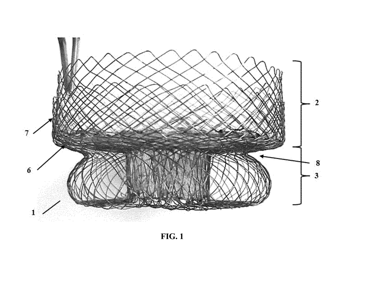
[0094]Referring to the drawings, FIG. 1 illustrates an anchoring device 1 made from a, preferably one single, flexible, compressible and expansible mesh and comprising an extraventricular part...


PUM


Abstract

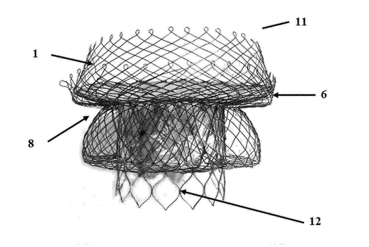
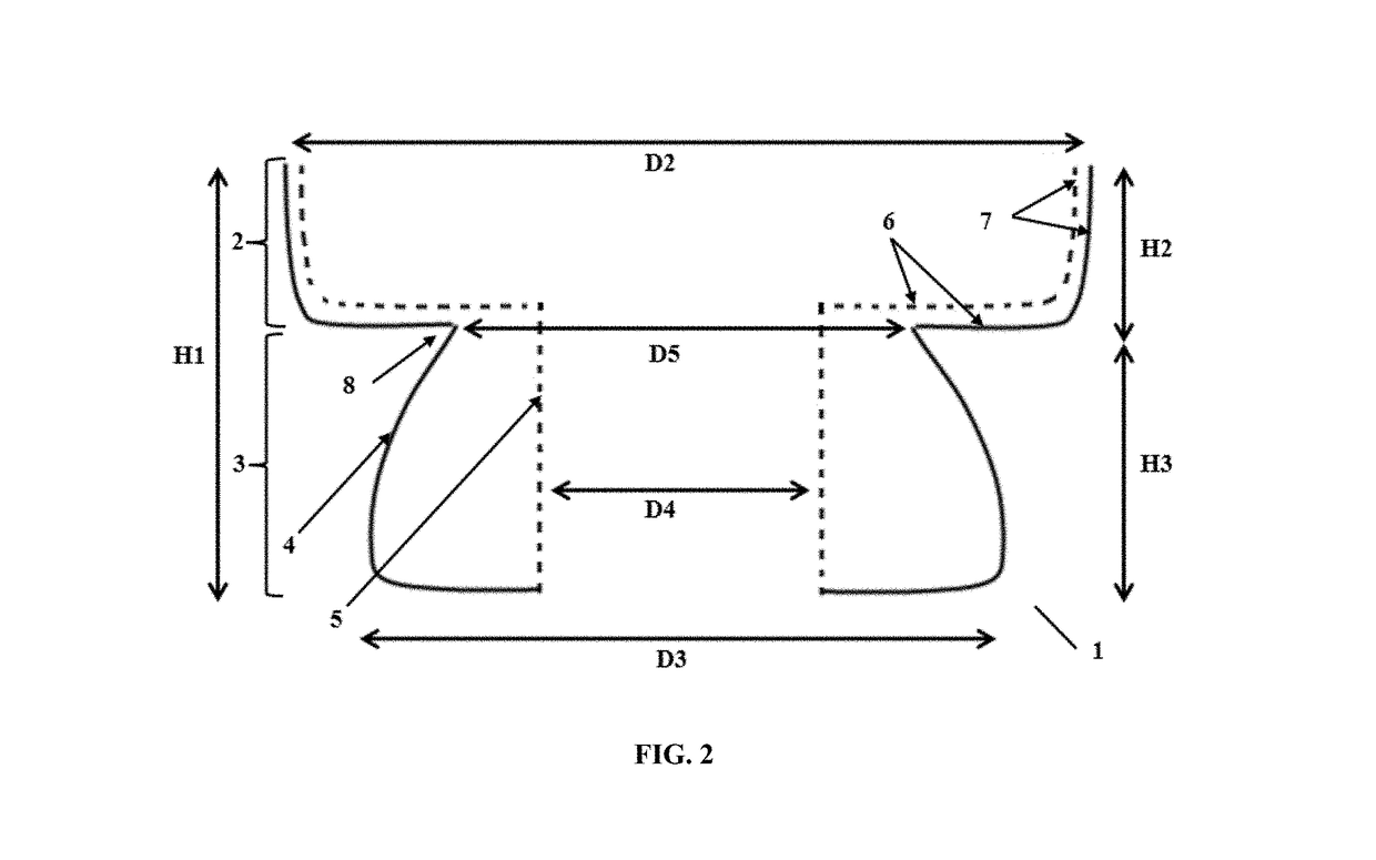
The present invention relates to an anchoring device (1) designed for anchoring a prosthetic heart valve inside a heart, comprising an extraventricular part (2) designed to be positioned inside an atrium or an artery and a ventricular part (3) designed to be positioned inside a ventricle, wherein the ventricular part comprises a double wall composed of an outer wall (4) and an inner wall (5) spaced apart at the level where the prosthetic heart valve is intended to be inserted, and wherein the anchoring device further comprises a predefined V-shaped groove (8) formed between the extraventricular part (2) and the ventricular part (3). The present invention also relates to an anchoring system (11) for anchoring a prosthetic heart valve inside a heart, comprising said anchoring device (1), a prosthetic heart valve support (12) and a prosthetic heart valve (13) connected to the prosthetic heart valve support (12).

Description

CROSS-REFERENCE TO RELATED APPLICATIONS[0001]This application is a continuation of U.S. patent application Ser. No. 15 / 112,311 filed on Jul. 18, 2016, which is a United States national phase application under 35 U.S.C. §371 of International Application No. PCT / EP2015 / 051037 filed on Jan. 20, 2015 and claims the benefit of EP Patent Application No. 14151825.8 filed on Jan. 20, 2014, the contents of which are herein incorporated in their entirety by reference. The International Application was published as International Publication No. WO 2015 / 107226 on Jul. 23, 2015.FIELD OF INVENTION[0002]The present invention relates to an anchoring device for a heart valve. More particularly the present invention relates to a self-expanding anchoring device designed for implantation of a prosthetic heart valve in a mammalian heart, preferably a human heart.BACKGROUND OF INVENTION[0003]Valvular heart disease is recognized as a common disease in the elderly population. Prevalence of valvular heart d...

Claims


Application Information

Patent Timeline
Patent Type & Authority Applications(United States)
IPC IPC(8): A61F2/24
CPCA61F2/2418A61F2/2436A61F2250/0069A61F2250/006A61F2230/0054A61F2250/0063A61F2250/0018
Inventor MARCHAND, CORALIERIOU, CECILE
Owner TRICARES SAS
Learn More