
System and Method for Preventing Cross-Contamination in Flow Generation Systems

a technology of flow generation system and flow control, applied in the direction of valves, respirators, mechanical equipment, etc., can solve the problems of main body of ventilator components, subsequently susceptible to contamination, improper function of ventilator components, etc., and achieve the effect of preventing cross-contamination

Active Publication Date: 2017-08-03
INVENT MEDICAL CORP
View PDF17 Cites 7 Cited by
  • Summary
  • Abstract
  • Description
  • Claims
  • Application Information

AI Technical Summary

Benefits of technology

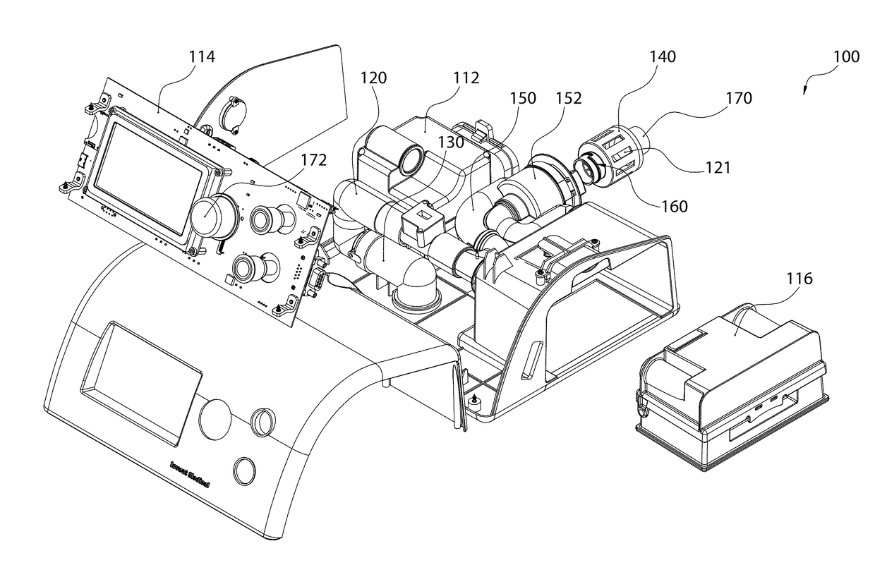
The patent describes a system for preventing cross-contamination in a flow generation apparatus. The system includes an airflow generator, a humidifier, and a cartridge that includes a bacterial filter and a check valve. The cartridge can be easily removed and replaced with a new cartridge. The system also includes a controller that regulates the flow of gas and a housing for the cartridge. The technical effects of this system include preventing gas from traveling through the exhalation circuit during the inhalation phase and preventing unfiltered gas from traveling through the exhalation circuit during the exhalation phase. The system also allows for the autoclaving of the cartridge and the performance of treatments on patients using the system for assisting breathing.

Problems solved by technology

However, in this configuration, since the hole(s) is not big enough to handle the entire exhalation flow, some of the exhaled flow travels back to the device.
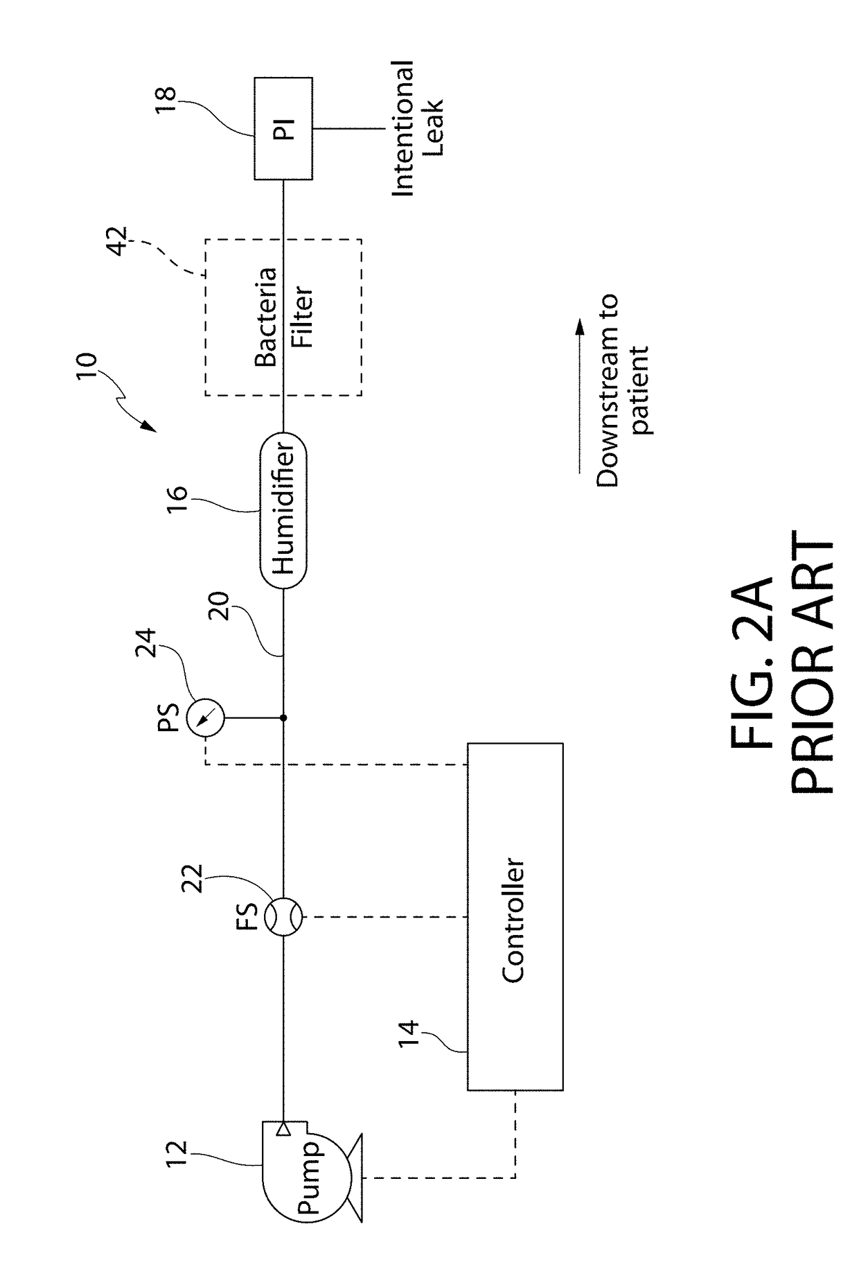
If the medical facility or patient fails to use bacteria filters, the main body of the ventilator components are exposed to the patient exhaled gas, and subsequently susceptible to contamination.
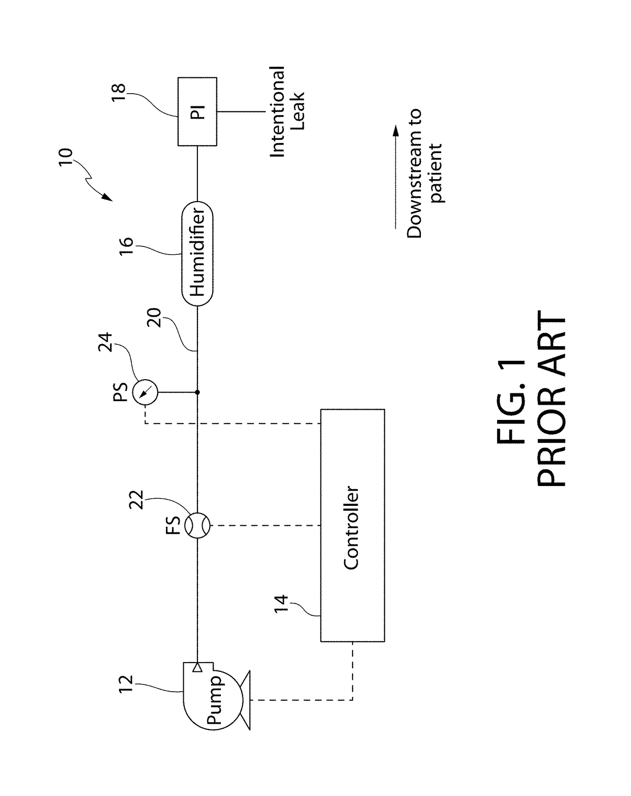
However, one issue with locating a bacteria filter downstream of the integrated humidifier is that water vapor in the gas often leads to improper function of ventilator components, negatively affecting proper ventilator function.
However, even for systems that utilize an external humidifier 16′, where the bacteria filter 42′ can be located between the ventilator outlet and the humidifier inlet, the chances of the bacteria filter 42′ being compromised due to the humidified gas will remain high, again affecting proper operation of the components of the ventilators.
In this case, ventilators and their components are naturally susceptible to contamination.

Method used


Image

  • System and Method for Preventing Cross-Contamination in Flow Generation Systems
  • System and Method for Preventing Cross-Contamination in Flow Generation Systems
  • System and Method for Preventing Cross-Contamination in Flow Generation Systems

Examples


Embodiment Construction

[0022]It is to be understood that the figures and descriptions of the present invention have been simplified to illustrate elements that are relevant for a more clear comprehension of the present invention, while eliminating, for the purpose of clarity, many other elements found in systems and methods of preventing cross-contamination in single-limb ventilators. Those of ordinary skill in the art may recognize that other elements and / or steps are desirable and / or required in implementing the present invention. However, because such elements and steps are well known in the art, and because they do not facilitate a better understanding of the present invention, a discussion of such elements and steps is not provided herein. The disclosure herein is directed to all such variations and modifications to such elements and methods known to those skilled in the art.

[0023]Unless defined otherwise, all technical and scientific terms used herein have the same meaning as commonly understood by ...


PUM


Abstract

A system for preventing cross-contamination in single-limb ventilators is described. In one embodiment, the system includes an airflow generator connected in-line to a humidifier, a first check valve and a patient interface by a gas flow circuit. A controller is electrically coupled to the airflow generator, and a cartridge is connected to the gas flow circuit between a first point downstream of the humidifier and a second point upstream of the patient interface. The cartridge includes a bacteria filter and the first check valve. A method for preventing cross-contamination in single-limb ventilators and a method for providing gaseous flow through a single-limb ventilator are also described.

Description

CROSS-REFERENCE TO RELATED APPLICATIONS[0001]This application claims priority to U.S. provisional application No. 62 / 288,058 filed on Jan. 28, 2016 incorporated herein by reference in its entirety.BACKGROUND OF THE INVENTION[0002]Flow generation systems can be generally described as systems that generate a gaseous flow, for example airflow or a blend of ambient air and oxygen. A ventilator is one example of a flow generation system. A ventilator is a piece of medical equipment that delivers a flow of gas, such as a blend of oxygen and ambient air to the airway of a patient to assist in or substitute a patient's breathing. Most ventilators deliver a blend of oxygen and air so that the patient receives a target oxygen concentration greater than that of ambient air. Generally, ventilators utilize a combination of single-use or reusable disposable components for the patient interface (e.g. a mask or mouthpiece connected to flexible tubing) and non-disposable capital equipment (e.g. air ...

Claims


Application Information

Patent Timeline
Patent Type & Authority Applications(United States)
IPC IPC(8): A61M16/08A61M16/12A61M16/20A61M16/10A61M16/00A61M16/16
CPCA61M16/0883A61M16/0069A61M16/16A61M16/208A61M16/1055A61M2016/0027A61M16/0875A61M16/1065A61M16/125A61M2016/003A61M16/205A61M16/022A61M2016/0039A61M2016/0036A61M2205/128A61M2205/123
Inventor CHANG, SAMUEL M.NGUYEN, NHIEN M.
Owner INVENT MEDICAL CORP
Learn More