Method of impact welding repair of hollow components

a hollow component and impact welding technology, applied in the field of gas turbines, can solve the problems of gas turbine components that are not readily weld-repaired, need replacement or repair, current gas turbine components continue to get damaged, etc., to prevent the deformation of the component and prevent the deformation of the cover plate

Inactive Publication Date: 2017-08-03
SIEMENS ENERGY INC
View PDF3 Cites 3 Cited by
  • Summary
  • Abstract
  • Description
  • Claims
  • Application Information

AI Technical Summary

Benefits of technology

[0010]A method of impact welding a flyer to a hollow component is provided. The method includes providing the component comprising a first material and including a cavity where a weld site is disposed on a first side of the component. The first material is selected from the group consisting of superalloys, stainless steels, and high temperature nickel based alloys. An incompressible material is packed against a second side of the component opposite the first side facing the cavity. A flyer comprising a second is positioned onto the weld site. The flyer is then impact welded to the component. The incompressible material prevents the deformation of the component during the impact welding. The second material is selected from the group consisting of superalloys, stainless steels, and high temperature nickel based alloys.
[0011]A method of impact welding a cover plate to a component including a cavity is provided. The method includes providing a component comprising a first material selected from the group consisting of superalloys, stainless steels, and high temperature nickel based alloys and including a cavity. The cavity is filled with

Problems solved by technology

However, current gas turbine components continue to get damaged from sustained exposure in the environment of the hot gas path and need either replacement or repair.
These gas turbine components are not readily weld-repaired by processes that cause melting of the substrate, for example, arc welding processes and beam welding processes.
Solidificati

Method used


Image

  • Method of impact welding repair of hollow components
  • Method of impact welding repair of hollow components
  • Method of impact welding repair of hollow components

Examples


Embodiment Construction

[0021]To facilitate an understanding of embodiments, principles, and features of the present disclosure, they are explained hereinafter with reference to implementation in illustrative embodiments. Embodiments of the present disclosure, however, are not limited to use in the described systems or methods.

[0022]The components and materials described hereinafter as making up the various embodiments are intended to be illustrative and not restrictive. Many suitable components and materials that would perform the same or a similar function as the materials described herein are intended to be embraced within the scope of embodiments of the present disclosure.

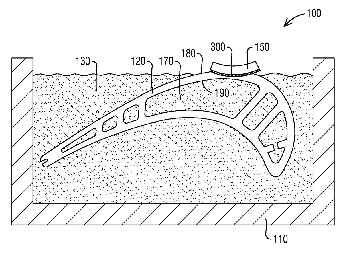
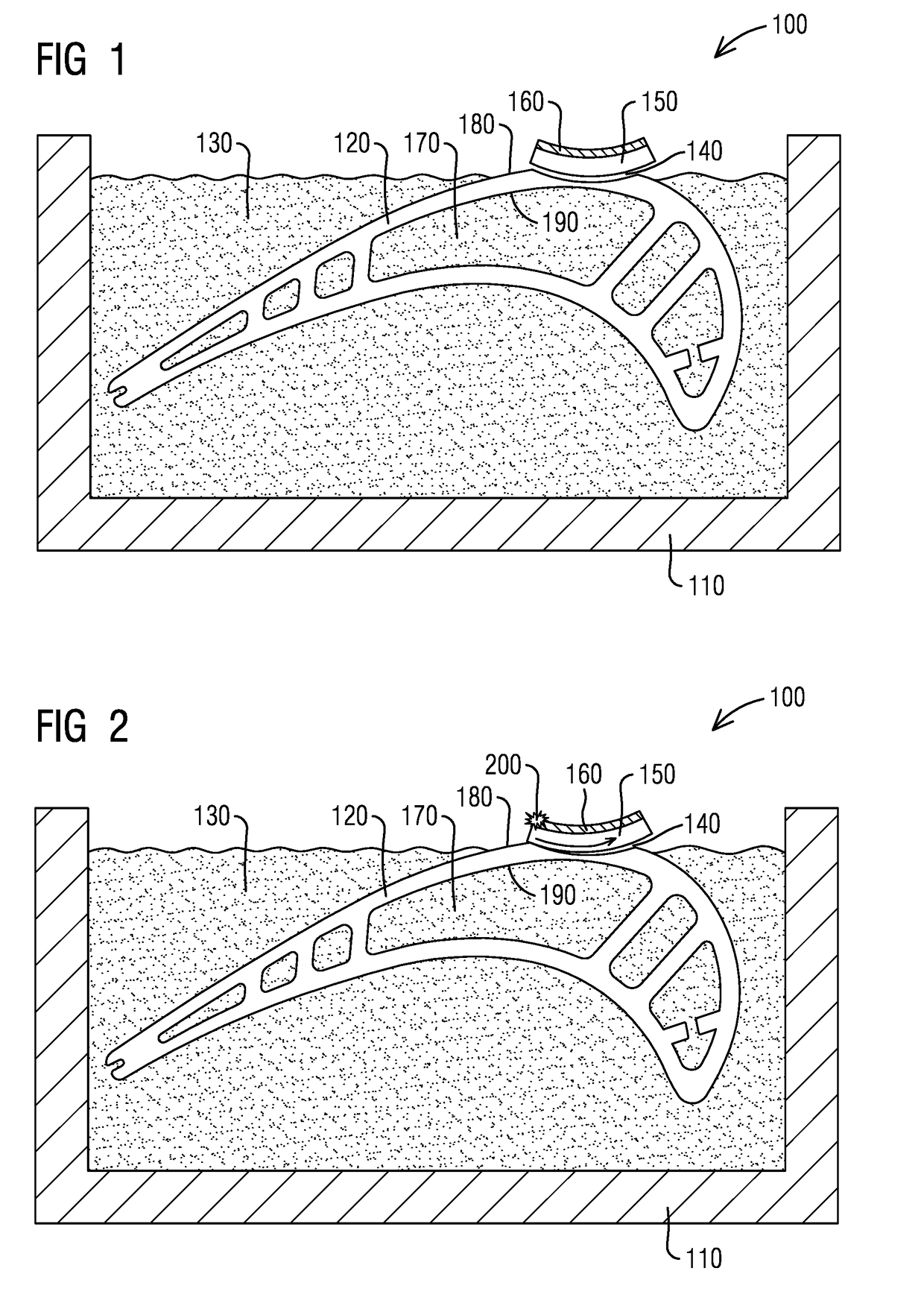
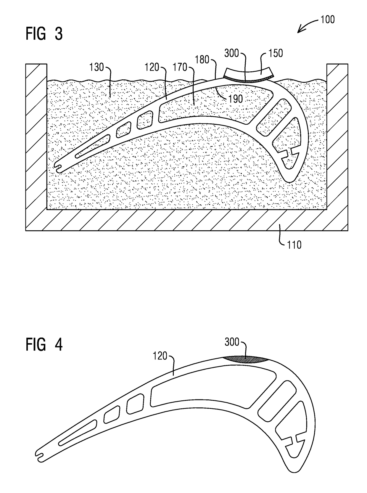
[0023]After long exposures to the hot and corrosive environment of the hot gas path of a gas turbine, many cast components become damaged requiring them to either be scrapped and replaced or repaired. Fusion weld processes as discussed above are used with limited success. A method of welding hollow components using solid state welding...


PUM

PropertyMeasurementUnit
Thicknessaaaaaaaaaa
Angleaaaaaaaaaa
Timeaaaaaaaaaa

Abstract

A method of impact welding a flyer to a hollow component is provided. The method includes providing the component made of a first material and including a cavity where a weld site is disposed on a first side of the component. An incompressible material is packed against a second side of the component opposite the first side facing the cavity. A flyer made of a second material is positioned onto the weld site. The flyer is then impact welded to the component. The incompressible material prevents the deformation of the component during the impact welding. A method of impact welding a cover plate to a component is provided as well as a support system for welding repair of hollow components.

Description

BACKGROUND[0001]1. Field[0002]The present application relates to gas turbines, and more particularly to a method of impact weld repair of hollow components. A support system for welding repair of components is also provided.[0003]2. Description of the Related Art[0004]Many cast gas turbine components, especially those along the hot gas path, are composed of high temperature materials as these materials can withstand an extremely hot and corrosive environment better than most other materials. However, current gas turbine components continue to get damaged from sustained exposure in the environment of the hot gas path and need either replacement or repair. These gas turbine components are not readily weld-repaired by processes that cause melting of the substrate, for example, arc welding processes and beam welding processes. Solidification and reheat cracking often result from such heat-dependent processes. Solid state welding provides an alternative to these processes such that these...

Claims


Application Information

Patent Timeline
IPC IPC(8): B23K20/06B23K20/24B23K20/26B23K20/00
CPCB23K20/06B23K20/002B23K2201/001B23K20/26B23K2203/05B23K20/24B23K20/08B23K20/165B23P6/005B23K2101/001B23K2103/05B23K2103/08
Inventor BRUCK, GERALD J.
Owner SIEMENS ENERGY INC
Why Eureka
Try Eureka