Synchronizing and braking mechanism for gripper jaws

Active Publication Date: 2017-08-03
PHD
View PDF1 Cites 2 Cited by
  • Summary
  • Abstract
  • Description
  • Claims
  • Application Information

AI Technical Summary

Benefits of technology

The present invention has several technical benefits. Firstly, it reduces the size and weight of the gripper, which in turn reduces the production cost and allows for its use in various operations. Secondly, it reduces the risk of damaging the workpiece or harming the user by reducing operation failure. Lastly, it improves synchronization of jaw motion.

Problems solved by technology

However, such methods used in the prior art to synchronize jaw motion result in an undesirable increase in the physical size, weight, and manufacturing cost of the gripper.
If power is lost while the gripper is in operation and gripping a workpiece, the resulting loss of grip force may lead to the possibility of a falling object.
Yet, the exterior location creates the undesirable effect of increasing the volume occupied by the gripper.

Method used


Image

  • Synchronizing and braking mechanism for gripper jaws
  • Synchronizing and braking mechanism for gripper jaws
  • Synchronizing and braking mechanism for gripper jaws

Examples


Embodiment Construction

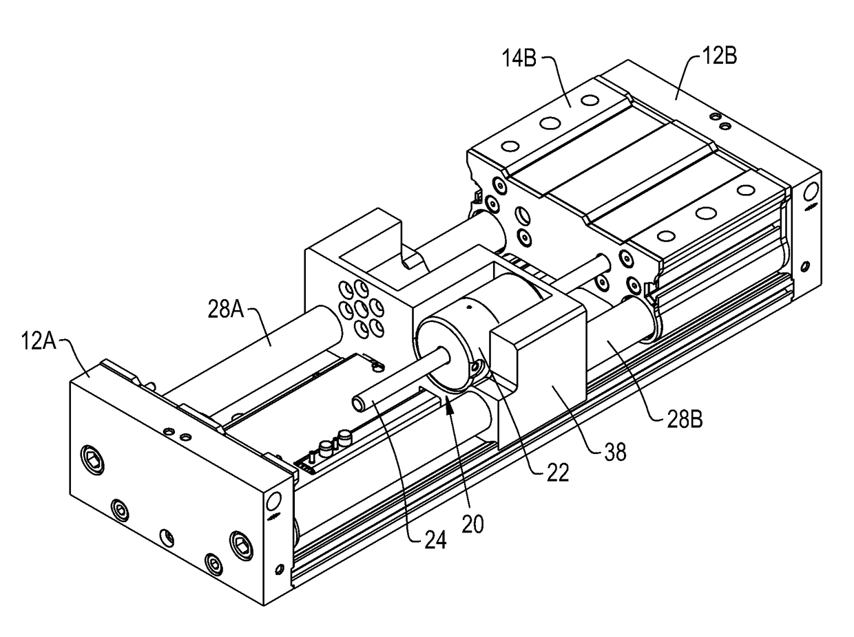
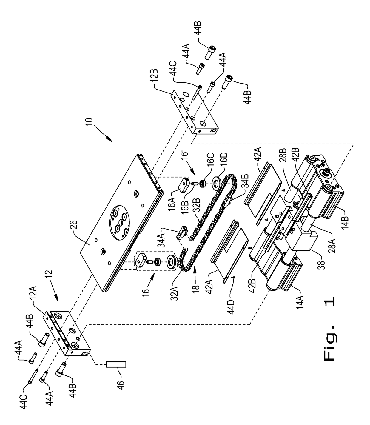
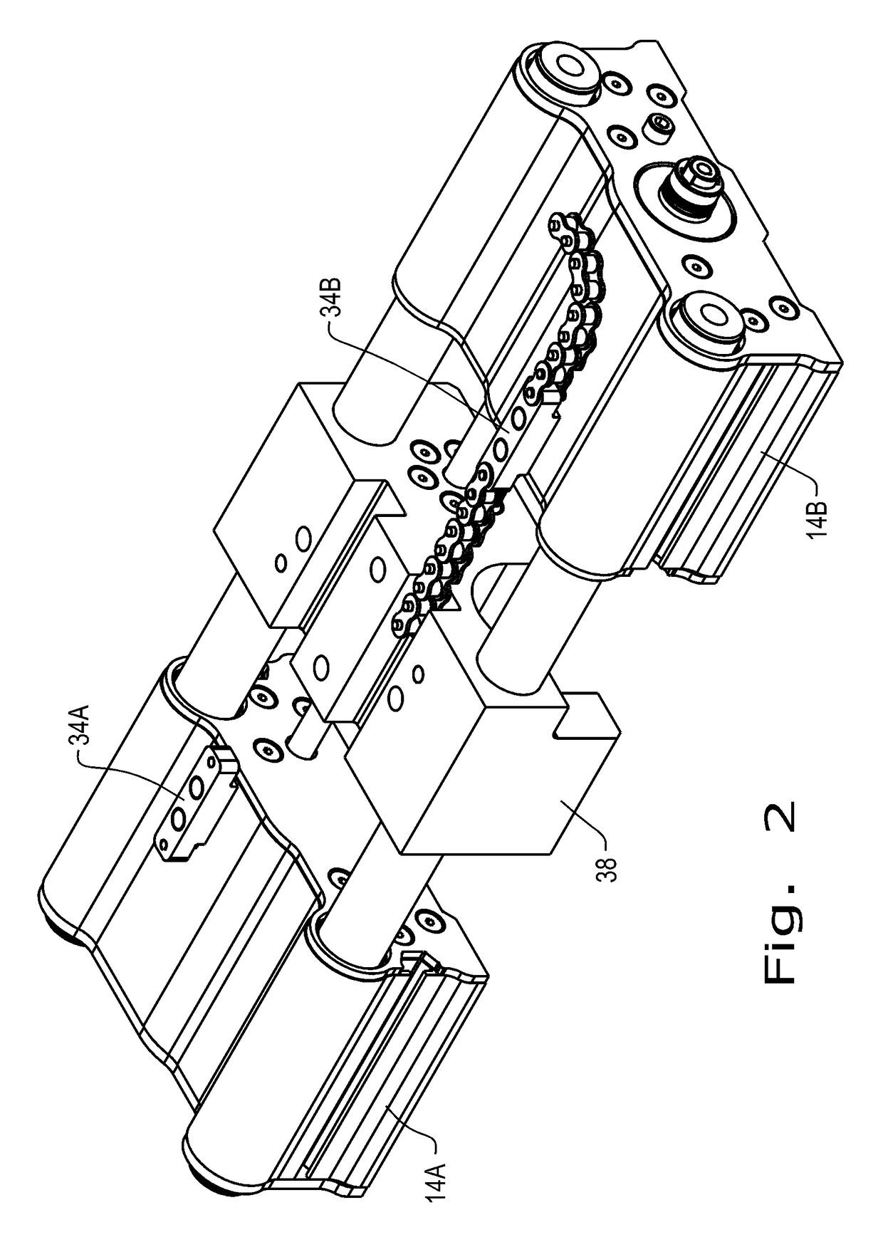
[0024]Referring now to FIGS. 1-7, there is shown an embodiment of a gripper 10 according to the present invention. The gripper 10 includes a main body 12, an actuating circuit, a first and second jaw 14A, 14B, a first and second pulley assembly 16, 16′, a chain loop 18, and a brake assembly 20 that has a brake 22 and a brake rod 24.

[0025]The main body 12 includes a first and a second endplate 12A, 12B. The endplates 12A and 12B are connected to each other by a baseplate 26 that extends between them. Two fasteners 44A are used to secure each endplate 12A, 12B to the baseplate 26. Two guide rails 28A, 28B extend between the first and second endplates 12A, 12B. Yet, a single guide rail may also be used (not shown). Fasteners 44B can be used to secure the guide rails 28A, 28B (FIG. 1). The main body 12 and the baseplate 26 may be composed of metal, a polymer material, or another desired material.

[0026]The actuating circuit includes at least one actuator 46 that is connected to the main ...


PUM


Abstract

A device for gripping an object that includes a main body having a first and a second endplate, a baseplate, at least one guide rail, and a first jaw and a second jaw, each receiving the at least one guide rail. The device also includes a first pulley assembly and a second pulley assembly respectively attached to the baseplate and a chain loop respectively attached to the first pulley assembly and the second pulley assembly. The chain loop includes a first chain length and a second chain length and a first link and a second link that attaches the first chain length and the second chain length. Each of the first link and second link include at least one dowel pin. The chain loop is attached to the first jaw and the second jaw by the at least one dowel pin of each of the first link and second link.

Description

CROSS REFERENCE TO RELATED APPLICATIONS[0001]This is a non-provisional application based upon U.S. provisional patent application Ser. No. 62 / 287,934, entitled “SYNCHRONIZING AND BRAKING MECHANISM FOR GRIPPER JAWS”, filed Jan. 28, 2016, which is incorporated herein by reference.BACKGROUND OF THE INVENTION[0002]1. Field of the Invention[0003]The present invention relates to mechanical grippers, and, more particularly, to the synchronization and braking of jaw tooling for such grippers.[0004]2. Description of the Related Art[0005]Grippers are mechanical devices characterized by one or more jaws that are moved together or apart by motive means such as an electric motor or pneumatic piston. Generally, the jaws of the gripper are attached to tooling that is responsible for transferring the force of the gripper to a workpiece such that the workpiece may then be held, moved, and / or rotated. This tooling may need to grasp workpieces that differ from one another in size, shape, draft, materi...

Claims


Application Information

Patent Timeline
IPC IPC(8): B25J19/00B25J15/00F16D63/00
CPCB25J19/0004B25J15/0023F16D63/008B25J15/083B25J15/0286
Inventor SIPE, ANDREW J.WILLIAMS, MATTHEW R.
Owner PHD
Why Eureka
Try Eureka