Transducer and reflector configurations for an acoustophoretic device

a technology of acoustophoretic devices and reflectors, which is applied in the direction of mechanical vibration separation, separation processes, instruments, etc., can solve the problems of high start-up cost of fed-batch bioreactors, filtering tends to be relatively expensive to manufacture, and non-functionality, etc., to reduce or eliminate non-productive downtime, improve yield, and reduce the effect of contamination in harves

Active Publication Date: 2017-08-03
FLODESIGN SONICS
View PDF6 Cites 7 Cited by
  • Summary
  • Abstract
  • Description
  • Claims
  • Application Information

AI Technical Summary

Benefits of technology

[0014]Disclosed herein are methods for separating a second fluid or a particulate from a host or primary fluid by flowing a mixture of the host fluid and the second fluid or particulate through an acoustophoretic device. The acoustophoretic device includes a chamber with an ultrasonic transducer coupled thereto. The acoustophoretic device may include a reflector opposite the ultrasonic transducer. The ultrasonic transducer can produce an ultrasonic wave that travels to the reflector. The reflector reflects the ultrasonic wave back to the transducer, which at certain frequencies, generates a standing wave with spatially stable nodes and antinodes. The ultrasonic transducer is operated to create a multi-dimensional acoustic standing wave in the chamber. The multi-dimensional acoustic standing wave may be generated by a planar, non-planar or combination transducer, and may emanate from a non-planar face of the transducer composed of piezoelectric material. The multi-dimensional acoustic standing wave in the chamber can trap or retain the second fluid or particulate on a continuous basis. The trapped second fluid or particulate agglomerates, aggregates, clumps, or coalesces together, and continuously rises or settles out of the host fluid due to enhanced buoyancy or gravity forces.

Problems solved by technology

A modern bioreactor tends to be a complex piece of equipment.
Such filters tend to be relatively expensive to manufacture and become clogged and non-functional as they retain material from the bioreactor as the material is processed.
However, a fed-batch bioreactor has high start-up costs, and generally has a large volume to obtain a cost-effective amount of product at the end of the growth cycle.
The processes for turning over a batch and preparing the bioreactor for a new batch often include large amounts of non-productive downtime.
The cell retention systems add a level of complexity to the perfusion process, where the process is carefully managed, controlled and maintained for successful operation.
Operational issues such as malfunction or failure of the cell retention equipment has previously been a problem with perfusion bioreactors, which has limited their attractiveness in the past.

Method used


Image

  • Transducer and reflector configurations for an acoustophoretic device
  • Transducer and reflector configurations for an acoustophoretic device
  • Transducer and reflector configurations for an acoustophoretic device

Examples


example 1

[0176]A polyolefin heat shrink film having a thickness of 0.60 mills (15.24 microns) was used as the acoustically transparent film to form a fluid-air interface, and was sandwiched in place using an empty transducer housing. This thickness is 1 / 50 of a wavelength when the transducer is operated at a frequency of 2.2 MHz. FIG. 22A is a picture of the test device.

[0177]FIG. 22B is a picture of the plastic film-air interface reflector during operation. The operation of a 5×5 trapping line mode can be seen through the plastic film, which is also optically transparent. The white trapping lines are visible through the plastic film. The overall efficiency of the apparatus dropped only 3% compared to using a steel reflector, which was within the range of measurement error.

example 2

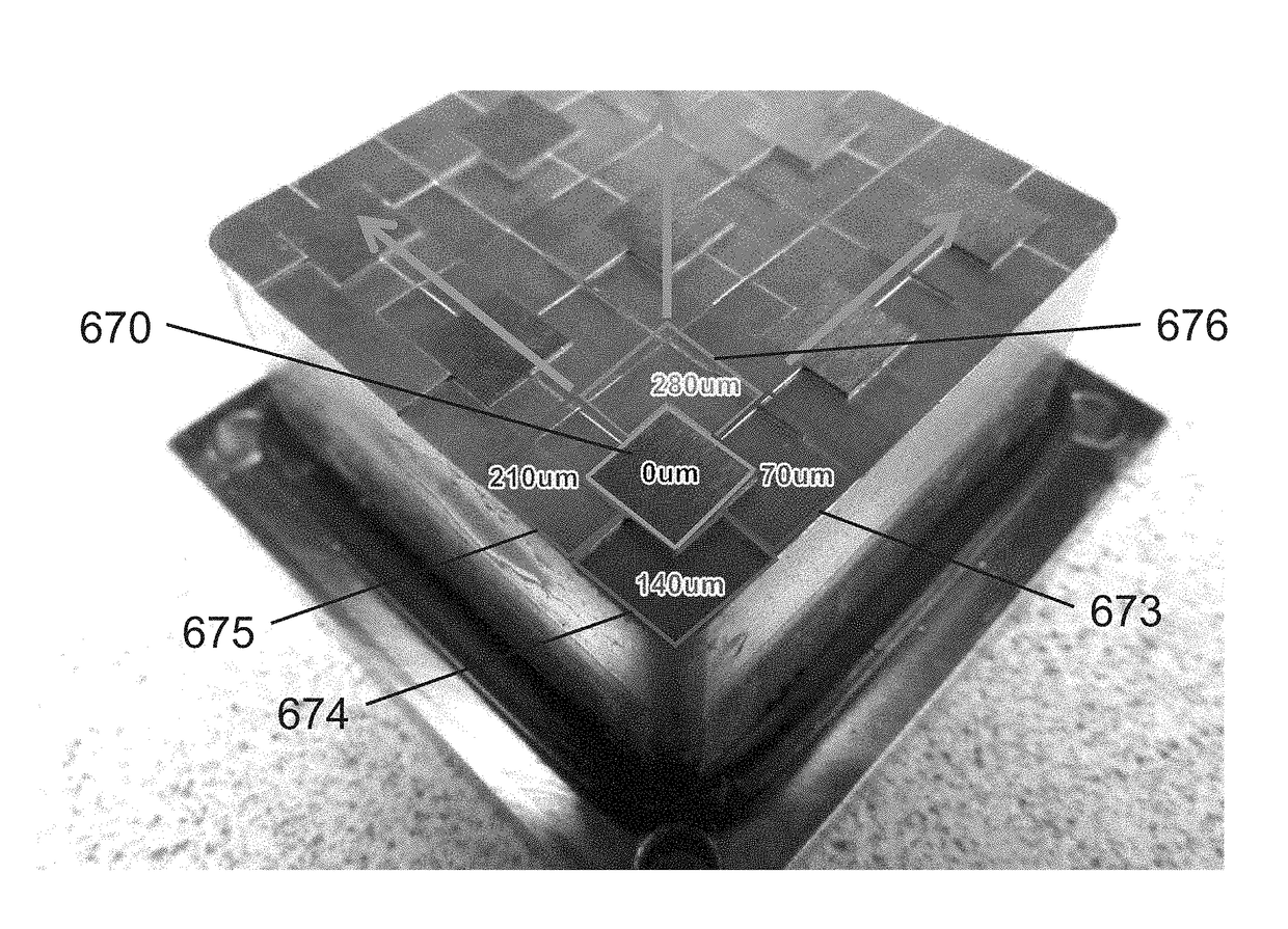
[0178]Acoustically transparent thin films 170 were attached to the face of the piezoelectric crystal (dimensions 1 inch by 1 inch) 172 of the ultrasonic transducer. Two different plastic thin films were used, one about 60 microns thick and one about 350 microns thick. A thin layer of ultrasonic transmission gel 174 was used to ensure there were no air pockets between the thin film and the crystal face. FIG. 24 is a picture of the square transducer and a diagram of the resulting structure. According to an example embodiment of the present disclosure, thin film 170 atop piezoelectric material 172 illustrated in FIG. 24 can be embossed and / or patterned to have a number of facets, similar to thin films discussed elsewhere herein. Such a non-planar thin film overlaid on piezoelectric material 172 can implement acoustic lensing for the transducer. The non-planar thin film can be configured and constructed to modulate the acoustic wave produced by piezoelectric material 172 to produce a de...


PUM

PropertyMeasurementUnit
frequencyaaaaaaaaaa
densityaaaaaaaaaa
thicknessaaaaaaaaaa

Abstract

Separation of particles or droplets from a host fluid may be achieved using a transducer and / or reflector that is a thin, non-planar structure. The thin non-planar structure improves operation of an acoustic standing wave generated by an acoustic transducer. The structure may operate as a pressure release boundary and may be constructed as plastic film.

Description

CROSS-REFERENCE TO RELATED APPLICATIONS[0001]The present application is a continuation-in-part of U.S. patent application Ser. No. 14 / 678,841, filed Apr. 3, 2015, now U.S. Pat. No. 9,623,348, issued Apr. 18, 2017, which claimed the benefit of U.S. Provisional Patent Application Ser. No. 61 / 975,035, filed Apr. 4, 2014, and which is a continuation-in-part of U.S. patent application Ser. No. 14 / 026,413, filed on Sep. 13, 2013, now U.S. Pat. No. 9,458,450, which is a continuation-in-part of U.S. Ser. No. 13 / 844,754, filed Mar. 15, 2013, which claimed the benefit of U.S. Provisional Patent Application Ser. No. 61 / 611,159, filed Mar. 15, 2012, and of U.S. Provisional Patent Application Ser. No. 61 / 611,240, also filed Mar. 15, 2012, and of U.S. Provisional Patent Application Ser. No. 61 / 708,641, filed on Oct. 2, 2012, and of U.S. Provisional Patent Application Ser. No. 61 / 754,792, filed Jan. 21, 2013. This application is also a continuation-in-part of U.S. patent application Ser. No. 15 / 20...

Claims


Application Information

Patent Timeline
Patent Type & Authority Applications(United States)
IPC IPC(8): C02F1/36C02F1/40B01D43/00B06B1/06B01D17/04
CPCC02F1/36B06B1/0622C02F1/40B01D43/00B01D17/04B01D17/041B01D17/044B01D19/0078B01D21/28B06B1/0644C12M35/04C12M47/02G10K11/28C12N1/02C12N13/00H10N30/2023
Inventor LIPKENS, BARTPRESZ, JR., WALTER M.CHITALE, KEDARMCCARTHY, BRIANROSS-JOHNSRUD, BENJAMINKENNEDY, III, THOMAS J.MEALEY, DANEDUTRA, BRIANSOKOLOWSKI, DAVID
Owner FLODESIGN SONICS
Why Eureka
Try Eureka