Compressor aerofoil

Active Publication Date: 2017-08-03
SIEMENS ENERGY GLOBAL GMBH & CO KG
View PDF1 Cites 14 Cited by
  • Summary
  • Abstract
  • Description
  • Claims
  • Application Information

AI Technical Summary

Benefits of technology

[0009]For these and other objectives and advantages there is provided a compressor aerofoil comprises a suction surface wall having a suction surface and a pressure surface wall having a pressure surface, the suction surface wall and the pressure surface wall meet at a leading edge and a trailing edge and define a tip having a tip surface, the aerofoil has a maximum thickness Tmax, a mean camber line is defined as passing through the leading edge and the trailing edge, the compressor aerofoil further comprises a winglet at the tip and which extends from the suction surface, the winglet has an overhang W that has a perpendicular extent from the suction surface in the range 0.1 Tmax to 1.5 Tmax, the winglet has a maximum overhang Wmax that occurs within 50% of the length of the mean camber line from the leading edge.
[0010]The winglet may have a leading portion and a trailing portion. The l

Problems solved by technology

The over-tip leakage flow results in large amounts of loss and blockage in the tip gap region of the compressor stage and which is detrimental to the stability and efficiency of compressors.
Th

Method used


Image

  • Compressor aerofoil
  • Compressor aerofoil
  • Compressor aerofoil

Examples


Embodiment Construction

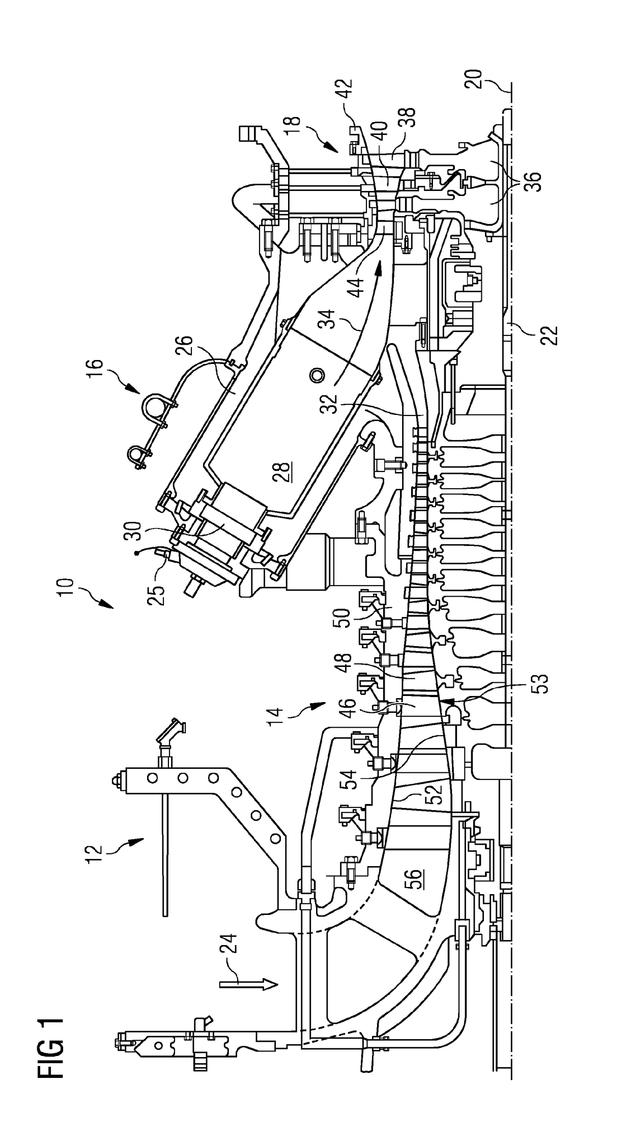
[0038]FIG. 1 shows an example of a gas turbine engine 10 in a sectional view. The gas turbine engine 10 comprises, in flow series, an inlet 12, a compressor section 14, a combustor section 16 and a turbine section 18 which are generally arranged in flow series and generally about and in the direction of a longitudinal or rotational axis 20. The gas turbine engine 10 further comprises a shaft 22 which is rotatable about the rotational axis 20 and which extends longitudinally through the gas turbine engine 10. The shaft 22 drivingly connects the turbine section 18 to the compressor section 14.

[0039]In operation of the gas turbine engine 10, air 24, which is taken in through the air inlet 12 is compressed by the compressor section 14 and delivered to the combustion section or burner section 16. The burner section 16 comprises a burner plenum 26, one or more combustion chambers 28 and at least one burner 30 fixed to each combustion chamber 28. The combustion chambers 28 and the burners ...


PUM


Abstract

A compressor aerofoil for a turbine engine or an axial process compressor, the compressor aerofoil includes a suction surface wall having a suction surface and a pressure surface wall having a pressure surface, the suction surface wall and the pressure surface wall meet at a leading edge and a trailing edge and define a tip having a tip surface, the aerofoil has a maximum thickness Tmax. A mean camber line is defined as passing through the leading edge and the trailing edge. The compressor aerofoil further includes a winglet at the tip and which extends from the suction surface, the winglet has an overhang W that has a perpendicular extent from the suction surface in the range 0.1 Tmax to 1.5 Tmax. The winglet has a maximum overhang Wmax that occurs within 50% of the length of the mean camber line from the leading edge.

Description

CROSS REFERENCE TO RELATED APPLICATIONS[0001]This application is the US National Stage of International Application No. PCT / EP2015 / 068856 filed Aug. 17, 2015, and claims the benefit thereof. The International Application claims the benefit of European Application No. EP14181280 filed Aug. 18, 2014. All of the applications are incorporated by reference herein in their entirety.FIELD OF INVENTION[0002]The present invention relates to a compressor aerofoil and in particular a configuration of a tip of the compressor aerofoil to minimise aerodynamic losses. The compressor aerofoil is either a rotor blade or a stator vane.BACKGROUND OF INVENTION[0003]A compressor of a gas turbine engine comprises rotor components, including rotor blades and a rotor drum, and stator components, including stator vanes and a stator casing. The compressor is arranged about a rotational axis with a number of alternating rotor blade and stator vane stages as is well known and each stage comprises an aerofoil. ...

Claims


Application Information

Patent Timeline
IPC IPC(8): F04D29/38
CPCF04D29/388F04D29/384F01D5/145F01D5/20F05D2240/303F05D2240/307F05D2240/306F04D29/164F04D29/324F04D29/544Y02T50/60
Inventor MCGILL, JOHNMILLER, ROBERTWELLS, ROGER
Owner SIEMENS ENERGY GLOBAL GMBH & CO KG
Why Eureka
Try Eureka