Double-walled pipe element and method for producing a double-walled pipe element

a technology of double-walled pipes and pipes, applied in the direction of spouting, bends, transportation and packaging, etc., can solve the problems of complex geometries and inability to achieve conventional manufacturing processes, and achieve the effect of simple and cost-effective production

Inactive Publication Date: 2017-08-03
AIRBUS DEFENCE & SPACE
View PDF5 Cites 15 Cited by
  • Summary
  • Abstract
  • Description
  • Claims
  • Application Information

AI Technical Summary

Benefits of technology

[0005]An object on which the present invention is based is to specify a pipe element suitable, in particular, for use in a fuel system of an aircraft which is producible simply and cost-effectively and, if required, with a complex geometry. Furthermore, an object on which the invention is based is to specify a method with which a pipe element suitable, in particular, for use in a fuel system of an aircraft, can be produced simply and cost-effectively and, if required, with a complex geometry.

Problems solved by technology

Furthermore, very complex geometries, such as, for example, undercuts or the like, which are not realizable with conventional manufacturing processes, can be produced by 3D printing.

Method used


Image

  • Double-walled pipe element and method for producing a double-walled pipe element
  • Double-walled pipe element and method for producing a double-walled pipe element
  • Double-walled pipe element and method for producing a double-walled pipe element

Examples


Embodiment Construction

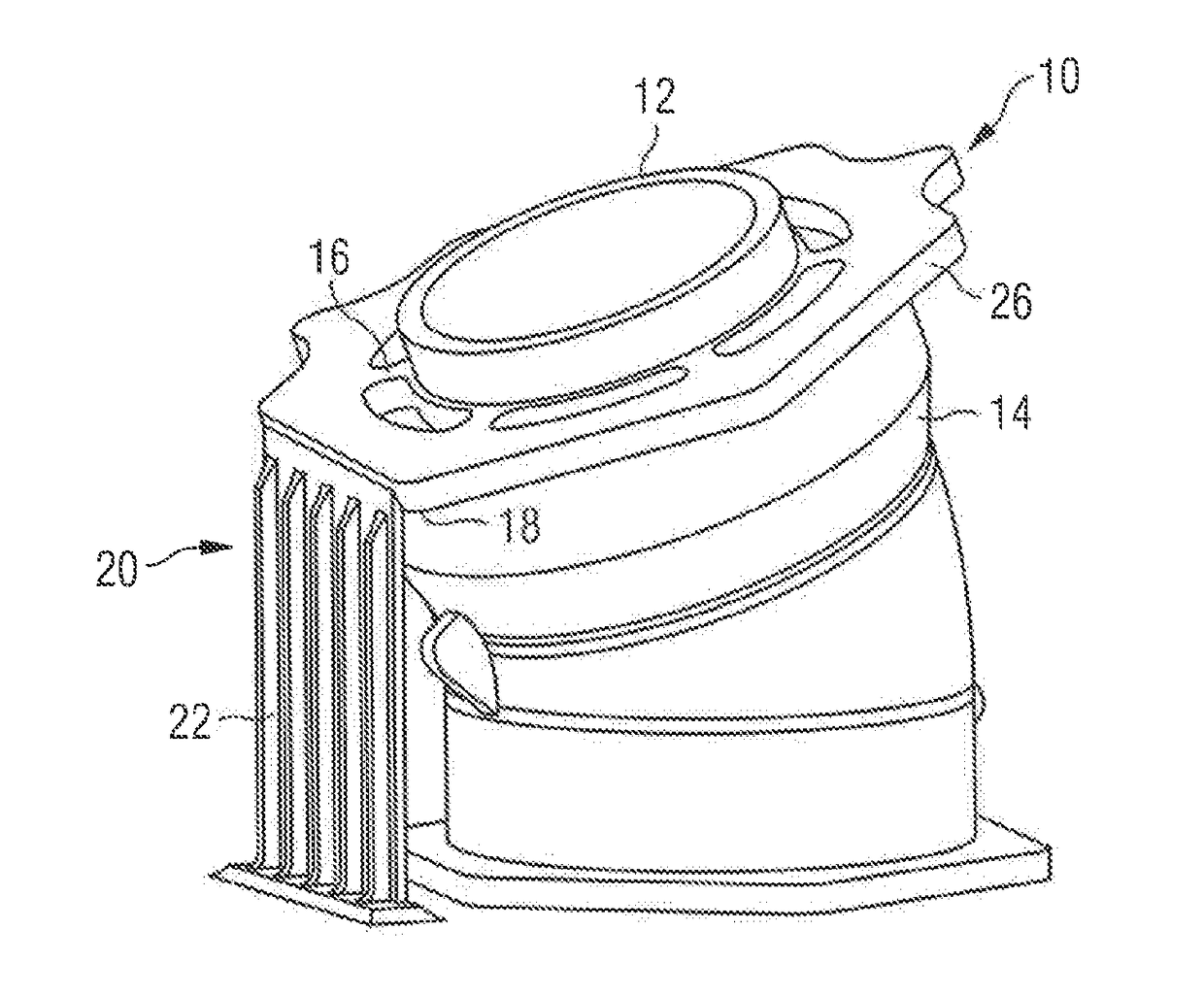
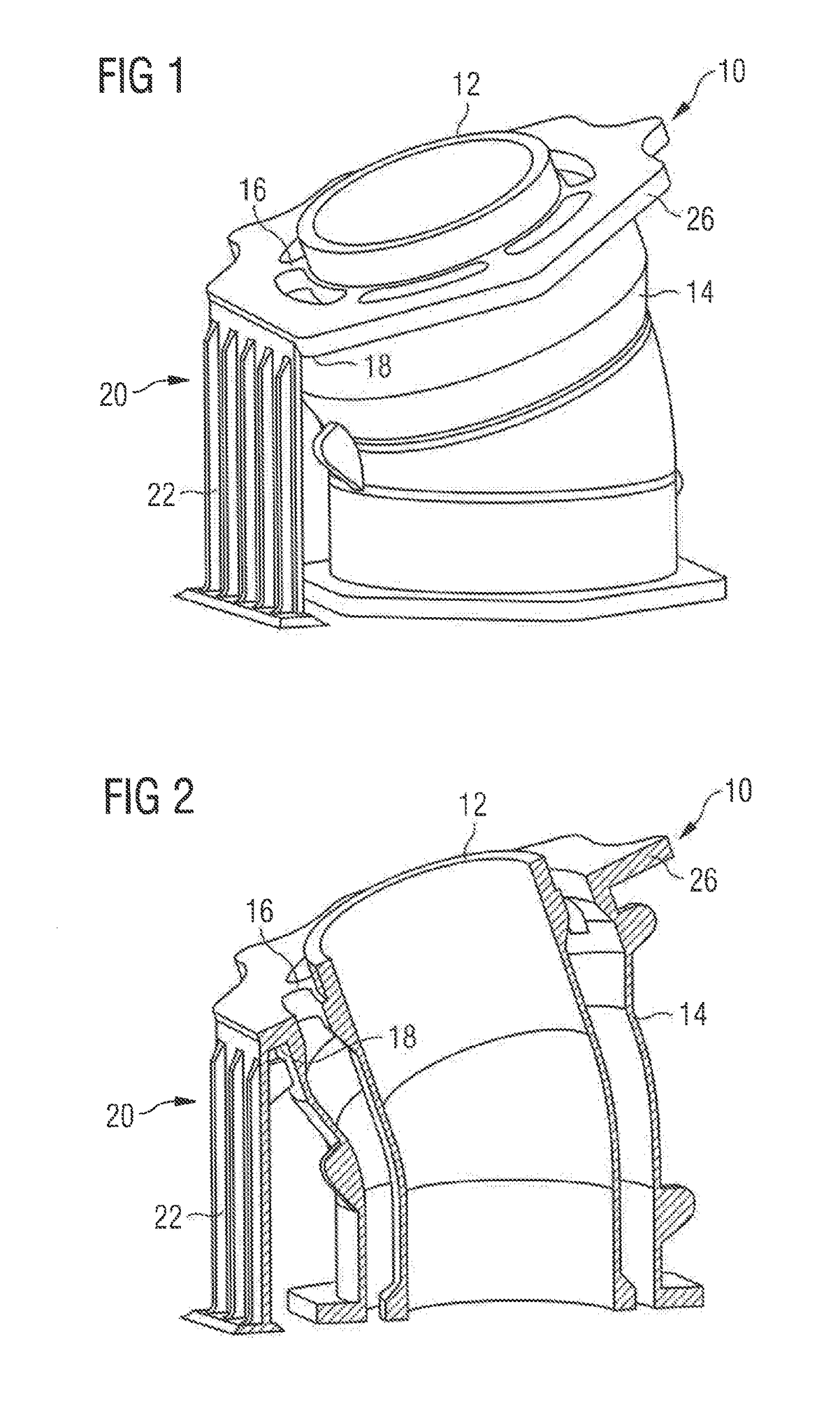
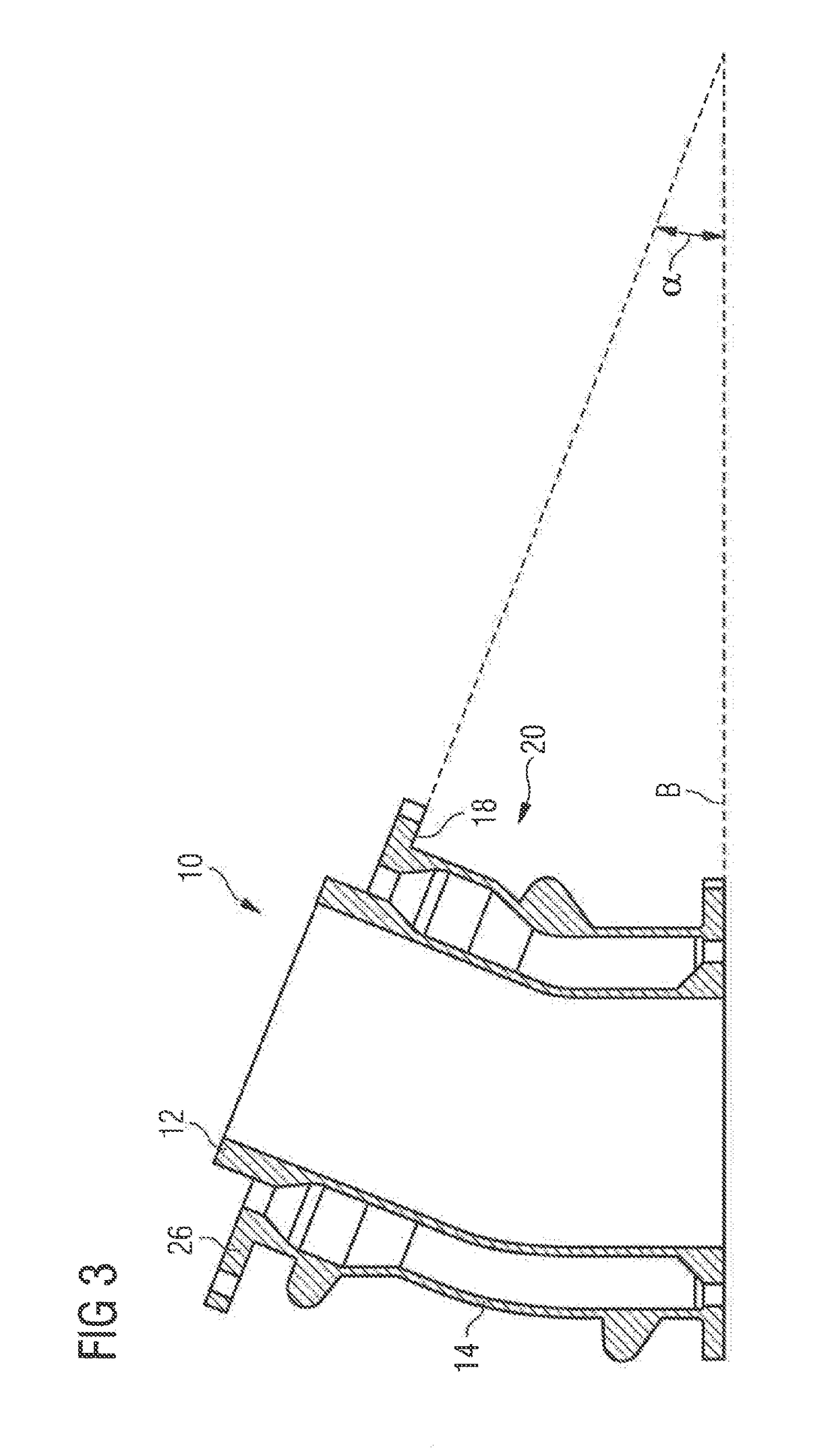
[0029]A pipe element 10 illustrated in FIGS. 1 to 3, which is provided for use in a fuel system of an aircraft, comprises an inner pipe 12. Furthermore, there is present an outer pipe 14 which sealingly surrounds the inner pipe 12 and is connected via webs 16 to the inner pipe 12. Such a design of the pipe element 10 ensures that, in the event of leakage, fuel escaping from the inner pipe 12 is caught in the outer pipe 14. The outer pipe 14 is connected to the aircraft surroundings via a suitable drainage system (not shown). In the event of leakage of the inner pipe 12, fuel caught in the outer pipe 14 can be safely discharged into the aircraft surroundings.

[0030]The pipe element 10 is constructed in one piece and produced by a 3D printing process. To produce the pipe element 10, a raw material powder layer is applied to a carrier and, depending on the desired geometry of the pipe element 10, subjected to laser radiation at selected locations. The laser is controlled by means of CAD...


PUM

PropertyMeasurementUnit
angleaaaaaaaaaa
angleaaaaaaaaaa
shapeaaaaaaaaaa

Abstract

A pipe element suitable for use in a fuel system of an aircraft comprises an inner pipe and an outer pipe sealingly surrounding the inner pipe and connected to the inner pipe. The pipe element is constructed in one piece and is produced by a 3D printing process.

Description

CROSS-REFERENCES TO RELATED APPLICATIONS[0001]This application claims the benefit of the German patent application No. 10 2016 201 547.8 filed on Feb. 2, 2016, and of the German patent application No. 10 2017 201 532.2 filed on Jan. 31, 2017, the entire disclosures of which are incorporated herein by way of reference.BACKGROUND OF THE INVENTION[0002]The present invention relates to a pipe element suitable, in particular, for use in a fuel system of an aircraft. Furthermore, the invention relates to a method for producing such a pipe element.[0003]Fuel-carrying pipes running through a pressurized fuselage region of an aircraft are usually of double-walled design, so that in the event of leakage, fuel escaping from an inner pipe is caught in an outer pipe. The outer pipe is connected to the aircraft surroundings via a suitable drainage system, whereby it is ensured that, in the event of leakage, fuel caught in the outer pipe can be safely discharged into the aircraft surroundings.[000...

Claims


Application Information

Patent Timeline
Patent Type & Authority Applications(United States)
IPC IPC(8): F16L9/19B64D37/00B33Y80/00B22F5/10B33Y10/00F16L43/00B22F3/105
CPCF16L9/19F16L43/001B64D37/005B33Y80/00B22F5/106B33Y10/00B22F3/1055F16L9/18Y02P10/25B22F10/28B22F10/47B22F10/66
Inventor KEDOR, FLORIANFISLAGE, TOBIASWOERDEMANN, RALFGRUETZMANN, CHRISTIAN
Owner AIRBUS DEFENCE & SPACE
Why Eureka
Try Eureka