Apparatus and method for x-ray phase contrast imaging

a phase contrast and x-ray technology, applied in the field of xray imaging, can solve the problems of shifting of interference pattern with current detectors, difficulty in directly imaging fine structures, etc., and achieve the effect of improving the determination of sine wave characteristics

Inactive Publication Date: 2017-08-03
UNIV OF MASSACHUSETTS
View PDF0 Cites 6 Cited by
  • Summary
  • Abstract
  • Description
  • Claims
  • Application Information

AI Technical Summary

Benefits of technology

[0023]In one more embodiment, the phase grating having a plurality of phase grating elements and the analyzer grating having a plurality of analyzer grating elements are configured such that a first phase shift is provided between a first of the plurality of phase grating elements and a first of the plurality of analyzer grating elements, a second phase shift is provided between a second of the plurality of phase grating elements and a second of the plurality of analyzer grating elements, and a third phase shift is provided by a third of the plurality of phase grating elements and a third of the plurality of analyzer grating elements. The phase shifts, which should cover a range of 2π radians, can be measured as a time sequence. While the range of phase shift we mention can be understood as having a range from 0 to 2π, it is also possible to use the range from −π to π radians, or in general, any range from angle R radians to R+2π radians. One needs to make at the minimum three measurements to meet the Nyquist sampling criterion. For example, for a sine wave covering the angular range [0,2π], the amplitudes at 0, π, and 2π will all be zero. Thus, it may be sufficient to measure at one of these points. The other two points one could in principle measure are π / 2 and 3π / 2 that correspond to the maximum and minimum amplitudes of the sine wave. However, as long as the angular relationship between the three measurements are known, and they are not all separated by exactly π radians, one can always determine the characteristics of the sine wave from the three measurements. The order in which the phase shift is measured is unimportant. As long as one knows which phase / analyzer grating combination is providing the measurement, one can determine the specific phase shift. Increasing the number of measured phase shifts can improve the determination of the characteristics of the sine wave.

Problems solved by technology

Since the shift is small, it is difficult to directly image the fine structures and the shifts in the interference pattern with current detectors.

Method used


Image

  • Apparatus and method for x-ray phase contrast imaging
  • Apparatus and method for x-ray phase contrast imaging
  • Apparatus and method for x-ray phase contrast imaging

Examples


first exemplary embodiment

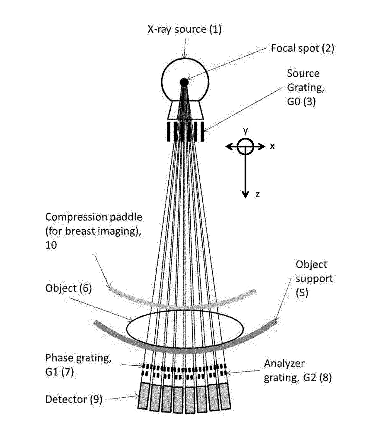
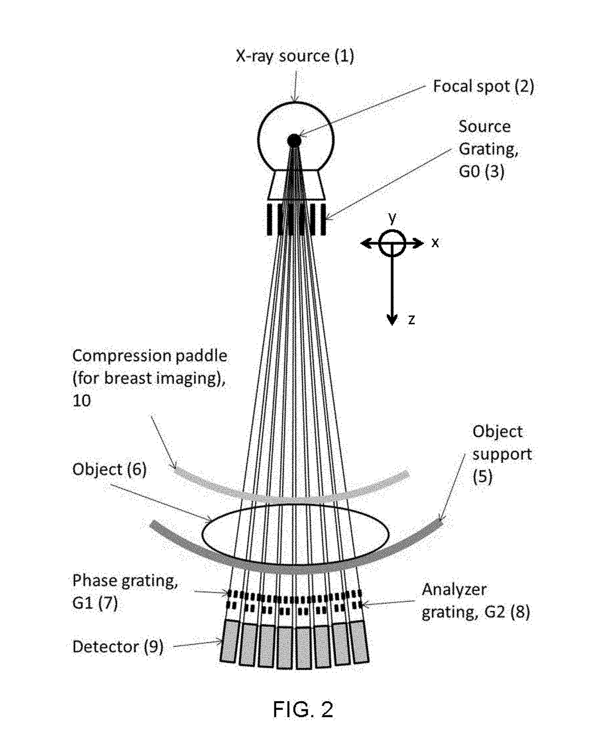
[0043]In this embodiment, the grating lines of all three gratings (G0, G1 and G2) are oriented orthogonal to the x-ray beam scan direction. This orientation of the gratings is illustrated in FIG. 2, and in FIG. 3A, FIG. 3B, FIG. 3C and FIG. 3D. A feature of the apparatus described in this embodiment is that the detector is sub-divided into N detector sub-assemblies. FIG. 2 shows an example having 8 detector sub-assemblies. Each detector sub-assembly having a corresponding phase grating (G1) and analyzer grating (G2). The phase grating (G1) and the analyzer grating (G2) are progressively displaced with respect to each other across the N detector sub-assemblies. The relative displacement of phase grating G1 and analyzer grating G2 is such that the over the N detector sub-assemblies measurements covering a phase shift of 2π is achieved. Alternatively stated, each detector sub-assembly provides a measure corresponding to a specific phase shift, and when measurements are performed over N...

second exemplary embodiment

[0049]In this embodiment, the grating lines of all three gratings (G0, G1 and G2) are oriented parallel to the scan direction. The analyzer grating G2 is tilted by a small angle with respect to the phase grating G1.

[0050]FIG. 7A is a schematic diagram that illustrates gratings G1 and G2 that are oriented such that the scan lines are parallel to the scan direction, and in which the gratings G2 and G1 are slightly tilted with respect to one another.

[0051]Referring to FIG. 7A, in which the tilt of G2 relative to G1 is exaggerated for illustration, pixels P(1,1) through P(1,5) each measure a different phase shift and the grating G2 is tilted such that the desired number of phase shifts covering integral multiples of 2π is achieved. As the object is scanned, assuming left to right motion in the figure, the object sampled by pixel P(1,5) that provides a measure corresponding to one phase shift is then sampled by pixel P(1,4) which provides a measure corresponding to a different phase shif...


PUM

PropertyMeasurementUnit
phase contrastaaaaaaaaaa
distanceaaaaaaaaaa
phaseaaaaaaaaaa

Abstract

An x-ray phase contrast imaging apparatus and method of operating the same. The apparatus passes x-rays generated by an x-ray source through, in succession, a source grating, an object of interest, a phase grating, and an analyzer grating. The x-ray source, the source grating, the phase grating, and the analyzer grating move as a single entity relative to an object of interest. The phase grating and the analyzer grating remain in fixed relative location and fixed relative orientation with respect to one another. The detected x-rays are converted to a time sequence of electrical signals. In some cases, the apparatus is controlled, and the electrical signals are analyzed by, by a general purpose programmable computer provided with instructions recorded on a machine readable medium. One or more x-ray phase contrast images of the object of interest are generated, and can be recorded or displayed.

Description

PRIORITY CLAIMS AND RELATED PATENT APPLICATIONS[0001]This application is the national phase of PCT / US13 / 26530, filed Feb. 15, 2013, which claims the benefit of priority from U.S. Provisional Application Ser. No. 61 / 602,923, filed on Feb. 24, 2012, the entire content of which is incorporated herein by reference in its entirety.STATEMENT OF FEDERALLY FUNDED RESEARCH[0002]This invention was made with government support under grant numbers. R21 CA134128 and R01 CA128906 awarded by the National Institutes of Health. The government has certain rights in the invention.TECHNICAL FIELD OF THE INVENTION[0003]The invention relates to x-ray imaging in general and particularly to x-ray imaging that employs phase contrast imaging methods.BACKGROUND OF THE INVENTION[0004]Clinical x-ray imaging techniques provide image contrast between the various tissues that comprise the anatomy being imaged through absorption contrast that is related to the x-ray attenuation properties of the tissues. These incl...

Claims


Application Information

Patent Timeline
Patent Type & Authority Applications(United States)
IPC IPC(8): G01N23/20A61B6/00G21K1/06G01N23/04
CPCG01N23/20075G01N23/04A61B6/484G01N2223/6126A61B6/4035A61B6/4291G21K1/067A61B6/4452G01N2223/313G01N23/041G21K2201/067H05G1/30
Inventor VEDANTHAM, SRINIVASANKARELLAS, ANDREW
Owner UNIV OF MASSACHUSETTS
Why Eureka
Try Eureka