
Detection device to identify markers dissolved in a liquid by means of a measurement of resistivity variation, detection method and use of marker and detection device

a detection device and resistivity variation technology, applied in the detection of reactive molecules, material thermal analysis, biochemistry apparatus and processes, etc., can solve the problems of limiting the applicability of markers in various applications, difficult processing, poor stability, etc., and achieves easy identification, good solubility, and low cost.

Active Publication Date: 2017-08-03
SICPA HLDG SA
View PDF0 Cites 2 Cited by
  • Summary
  • Abstract
  • Description
  • Claims
  • Application Information

AI Technical Summary

Benefits of technology

The present invention aims to provide a cost-effective and portable solution for detecting a low concentration marker in a liquid, such as fuel, with good solubility. The marker should be difficult to extract and separate, and easy to identify with special equipment. The solution should be able to detect the presence of a marker in a liquid quickly, within a few minutes or less. Additionally, the invention seeks to provide a method for authenticating the origin and authenticity of a liquid, such as fuel, that is easy to implement and provides a higher security level than conventional methods.

Problems solved by technology

However, conductive polymers are generally difficult to process and have poor stability, which greatly limits their applicability in various applications.
For an application to detect markers in a liquid, the currently available conductive polymers typically exhibit stability problems, as the original physical shape undergoes variations as a consequence of the contact with liquids, particularly at increasing temperature, and in organic solvents.
This shape variation causes a variation of the electrical properties and a degradation of the polymer during storage.
Yet, often bulky and expensive equipment is needed in order to detect the marker.
In another aspect, the marking can be easily counterfeited if commercially available substances (e.g. dyes) are used, as only the properties of the marker (but not its interaction with a detection device) are assessed.

Method used


Image

  • Detection device to identify markers dissolved in a liquid by means of a measurement of resistivity variation, detection method and use of marker and detection device
  • Detection device to identify markers dissolved in a liquid by means of a measurement of resistivity variation, detection method and use of marker and detection device
  • Detection device to identify markers dissolved in a liquid by means of a measurement of resistivity variation, detection method and use of marker and detection device

Examples


Embodiment Construction

[0166]The inventors performed several experiments in order to identify suitable de-dopant molecules (markers) and to assess the sensitivity and accuracy of the method / device. The markers evaluated in the experiments on different conductive polymeric formulations are listed in table 1 and 2; and the further possible markers suitable for the application to carry out the invention are listed in table 3.

[0167]In parallel, the influence of the insulating polymer on the absorption of the marker in the fuel has been evaluated. The insulating polymer strongly influences the ability of the conductive polymer to decrease its conductivity. The inventors prepared and studied different polymeric formulations listed in table 4. The markers listed in table 1 have been tested depositing a 2 μl drop on the conductive polymer which is positioned as a path (or “bridge” which does not need to be suspended over any substrate) between two conductive pads present on a PCB having a distance of 1 mm. The el...


PUM

PropertyMeasurementUnit
Fractionaaaaaaaaaa
Fractionaaaaaaaaaa
Fractionaaaaaaaaaa

Abstract

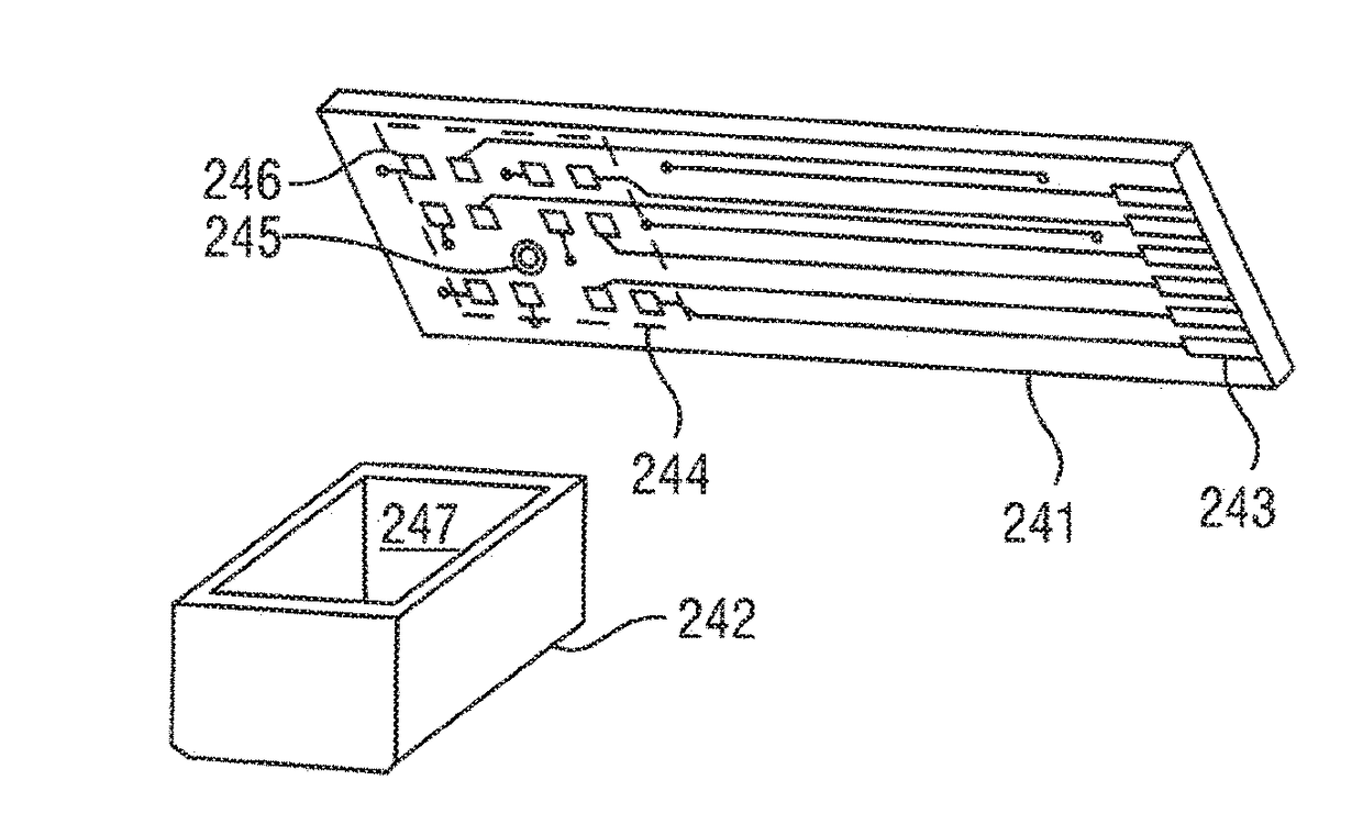
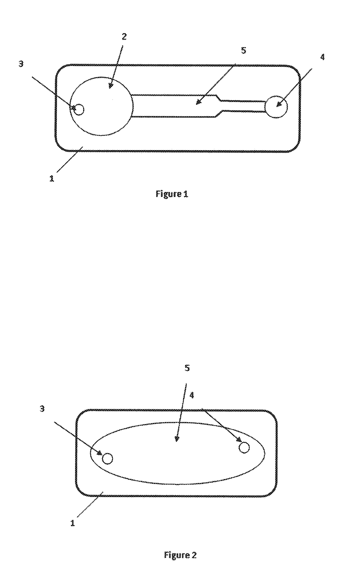
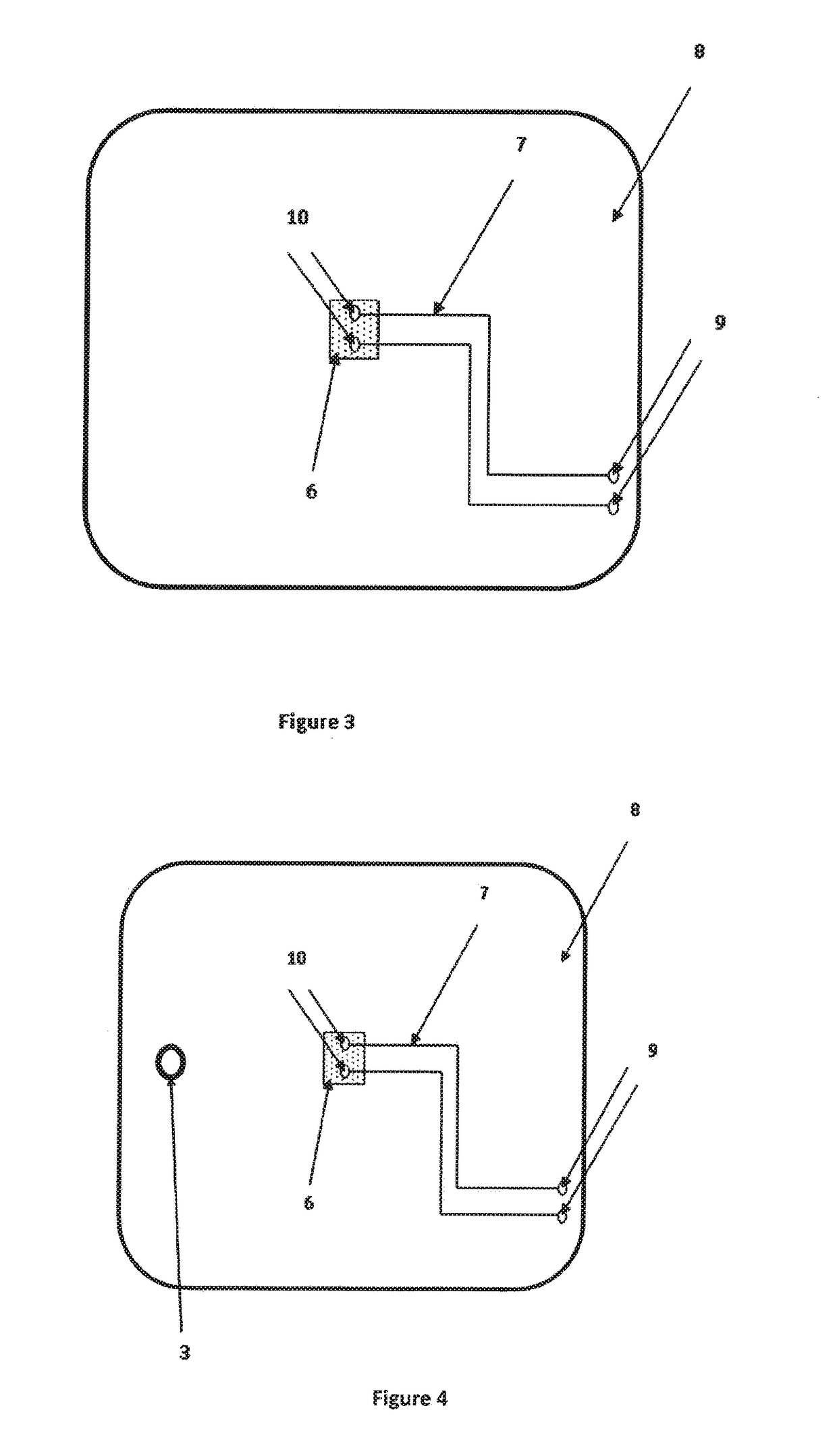
A detection device for detecting a marker in a liquid, preferably a fuel, comprising:a reaction chamber 5, provided with a de-dopable conductive polymer 6 building a path between two conductive pads 10 connected to a resistivity measurement device, wherein the de-dopable conductive polymer 6 is able to be de-doped by a chemical reaction with the marker, changing its resistivity.

Description

TECHNICAL FIELD[0001]The technical field is the detection of reactive molecules in a liquid environment. These reactive molecules can act as marker for the liquid, serving as authentication means for verifying the authenticity and / or origin of the liquid.BACKGROUND OF THE INVENTION[0002]Conductive polymers are presently known materials. Also, conductive polymers are partly commercially available. They are currently considered as material for integrated circuits, light emitting devices, antistatic materials, displays and batteries.[0003]However, conductive polymers are generally difficult to process and have poor stability, which greatly limits their applicability in various applications. For an application to detect markers in a liquid, the currently available conductive polymers typically exhibit stability problems, as the original physical shape undergoes variations as a consequence of the contact with liquids, particularly at increasing temperature, and in organic solvents. This ...

Claims


Application Information

Patent Timeline
IPC IPC(8): G01N33/487G01N33/28G01N27/12
CPCG01N33/48707G01N33/2882G01N27/126G01N33/4836G01N27/26G01N33/2835G01R27/02B01L3/502707B01L7/00B01L2200/12B01L2300/0645B01L2300/0816B01L2300/0887B01L2300/1827B01L2400/0415B01L2400/0421C12Q1/001C12Q1/6834G01N27/3276G01N27/4473G01N27/44791
Inventor CIAMPINI, DAVIDE
Owner SICPA HLDG SA
Learn More