
Compact digital holographic microscope for planetary imaging or endoscopy

a planetary imaging or endoscopy technology, applied in the field of compact digital holographic microscopes for planetary imaging or endoscopy, can solve the problems of difficult direct observation of prokaryotes (bacteria and archaea) in their native environment, complex objective lenses with tight alignment tolerances, and limited depth-of-field of conventional high-resolution microscopes capable of imaging bacteria

Active Publication Date: 2017-08-03
CALIFORNIA INST OF TECH
View PDF2 Cites 9 Cited by
  • Summary
  • Abstract
  • Description
  • Claims
  • Application Information

AI Technical Summary

Benefits of technology

The present patent describes an imaging system that uses gradient-index lenses or optical fibers to create interference fringes on a camera. The system can create high-resolution images of samples or electric field maps. The technical effects of the invention include improved image quality, reduced aberration, and improved depth of field. The imaging system can be used in digital holographic microscopy and has applications in biological research and medical diagnostics.

Problems solved by technology

Conventional high-resolution microscopes capable of imaging bacteria have limited depth-of-field and typically require complex objective lenses with tight alignment tolerances.
As a result, direct observation of prokaryotes (bacteria and archaea) in their native environments has yet to be performed in most parts of the Arctic and Antarctic, around hydrothermal vents, and in the majority of the open ocean [1].
For example, use of incoherent light provides speckle noise reduction [15], but also reduced fringe visibility and depth of field.
On-chip systems can provide a large field of view (FOV) by situating the sample very close to the detector array [21-23], but thermal issues can arise from differing ambient-sample and powered-detector temperatures.
Of these, laser-based systems [14, 24-26] have tended to include pinholes and additional fore-optics to increase the laser-beam numerical aperture (NA), thereby increasing system volume and alignment complexity.

Method used


Image

  • Compact digital holographic microscope for planetary imaging or endoscopy
  • Compact digital holographic microscope for planetary imaging or endoscopy
  • Compact digital holographic microscope for planetary imaging or endoscopy

Examples


Embodiment Construction

[0037]In the following description of the preferred embodiment, reference is made to the accompanying drawings which form a part hereof, and in which is shown by way of illustration a specific embodiment in which the invention may be practiced. It is to be understood that other embodiments may be utilized and structural changes may be made without departing from the scope of the present invention.

Technical Description

[0038]I. Example Digital Holographic Microscopy with GRIN Lenses

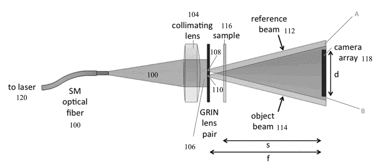
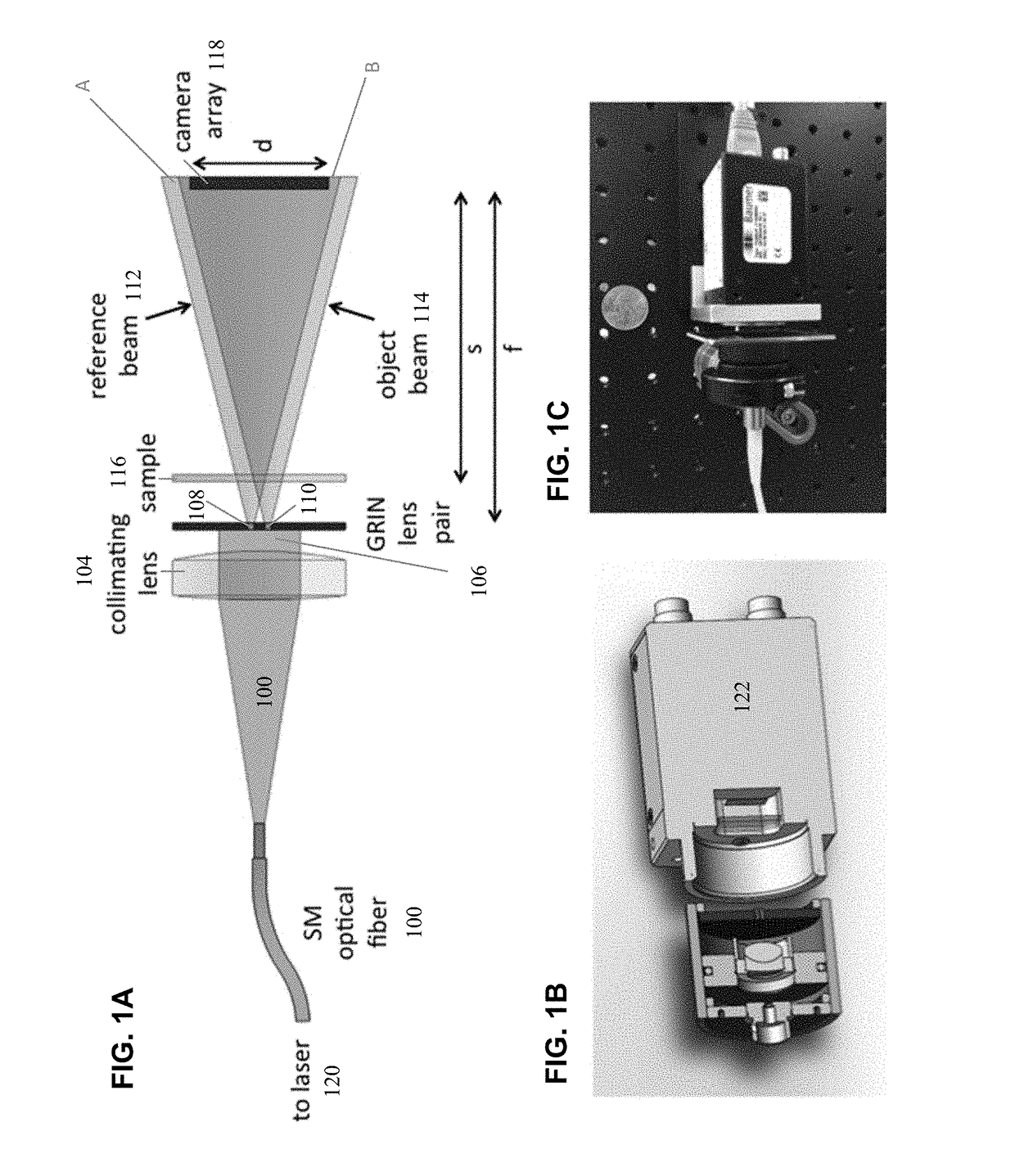
[0039]In lensless holography, reference and source beams directly illuminate the detector array, without any intervening optics. However, as in standard microscopy, high-resolution holographic microscopy also requires high NA, as the linear resolution is still given by λ / (2NA). High-NA laser beams must then be launched from just in front of the detector array, i.e., from a distance, f, of ≈1-3 cm for a typical cm-scale array. Moreover, in the off-axis holography case, the fringes on the detector array due t...


PUM


Abstract

In situ investigation of microbial life in extreme environments can be carried out with microscopes capable of imaging 3-dimensional volumes and tracking particle motion. A lensless digital holographic microscope is disclosed that provides roughly 1.5 micron resolution in a compact, robust package suitable for remote deployment. High resolution is achieved by generating high numerical-aperture input beams with radial gradient-index rod lenses. The ability to detect and track prokaryotes was explored using bacterial strains of two different sizes. In the larger strain, a variety of motions were seen, while the smaller strain was used to demonstrate a detection capability down to micron scales.

Description

CROSS REFERENCE TO RELATED APPLICATIONS[0001]This application claims the benefit under 35 U.S.C. Section 119(e) of the following co-pending and commonly-assigned U.S. Provisional patent applications:[0002]U.S. Provisional Patent Application No. 62 / 289,682, filed Feb. 1, 2016, by Eugene Serabyn, Christian A. Lindensmith, James K. Wallace, Kurt M. Liewer, and Jay L. Nadeau, entitled “COMPACT DIGITAL HOLOGRAPHIC MICROSCOPE FOR PLANETARY IMAGING OR ENDOSCOPY,” ref. No. (CIT 7437-P); and[0003]U.S. Provisional Patent Application No. 62 / 365,293, filed Jul. 21, 2016, by Eugene Serabyn, Christian A. Lindensmith, James K. Wallace, Kurt M. Liewer, and Jay L. Nadeau, entitled “A COMPACT LENSLESS HOLOGRAPHIC MICROSCOPE,” ref. No. CIT-7572-P[0004]both of which applications are incorporated by reference herein.[0005]This application is related to U.S. Utility patent application Ser. No. 14 / 939,389, filed on Nov. 12, 2015, by Kurt M. Liewer, Christian A. Lindensmith, Eugene Serabyn, Stephanie Rider...

Claims


Application Information

Patent Timeline
IPC IPC(8): G03H1/00G02B23/24G03H1/04G02B21/36G02B3/00F21V8/00
CPCG03H1/0005G03H2001/0436G02B6/0005G03H1/0443G03H1/0465G03H1/0402G02B21/365G02B23/2469G02B23/2484G03H2001/005G03H2001/0452G03H2001/0471G03H2223/17G03H2222/52G03H2001/0469G02B3/0087G02B6/0006G02B6/0008G02B23/26G03H2001/0445
Inventor SERABYN, EUGENELINDENSMITH, CHRISTIAN A.WALLACE, JAMES K.LIEWER, KURT M.NADEAU, JAY L.
Owner CALIFORNIA INST OF TECH
Learn More