Method for Imprinting and Erasing Amorphous Metal Alloys

a technology imprinting, which is applied in the field of imprinting and erasing amorphous metal alloys, can solve the problems of reducing the mechanical properties of amorphous metal alloys, limiting the processing time of hot-forming operations, and unable to form now

Active Publication Date: 2010-04-22
YALE UNIV
View PDF5 Cites 47 Cited by
  • Summary
  • Abstract
  • Description
  • Claims
  • Application Information

AI Technical Summary

Benefits of technology

[0040]It is a feature of the invention that surface roughness of amorphous metal alloy substrates is smoothened by heating the amorphous metal into the supercooled liquid region and roughness is smoothened under the action of the surface tension alone.

Problems solved by technology

Heating the bulk solidifying alloy beyond the crystallization temperature leads to crystallization and immediate loss of the superior properties of the alloy and it can no longer be formed.
First, it degrades the mechanical properties of the amorphous metal alloy.
From a processing standpoint, crystallization limits the processing time for hot-forming operation because the flow in crystalline materials is order of magnitude higher than in the liquid amorphous metal alloy.
However, these applications are still limited by the difficulties associated with net-shape fabrication.
The first processing method, direct casting of three-dimensional components, requires simultaneous filling and fast cooling of complex dies, which makes high aspect ratio geometries challenging.
Furthermore, direct casting relies on wetting of the mold material by the amorphous metal alloy, which limits for example the use of silicon as a mold material and is not compatible with most of MEMS fabrication methods.
However, this imposes several major limitations to further improvement of current imprint lithography techniques, including (1) short useful lifetime of the mold; (2) low printing speed; and (3) solubility of the imprint media in organic solutions.
Heating and cooling cycles and high pressure (approximately 50-130 bar), applied during embossing, produce stress and wear on the nanoimprint molds.

Method used


Image

  • Method for Imprinting and Erasing Amorphous Metal Alloys
  • Method for Imprinting and Erasing Amorphous Metal Alloys
  • Method for Imprinting and Erasing Amorphous Metal Alloys

Examples


Embodiment Construction

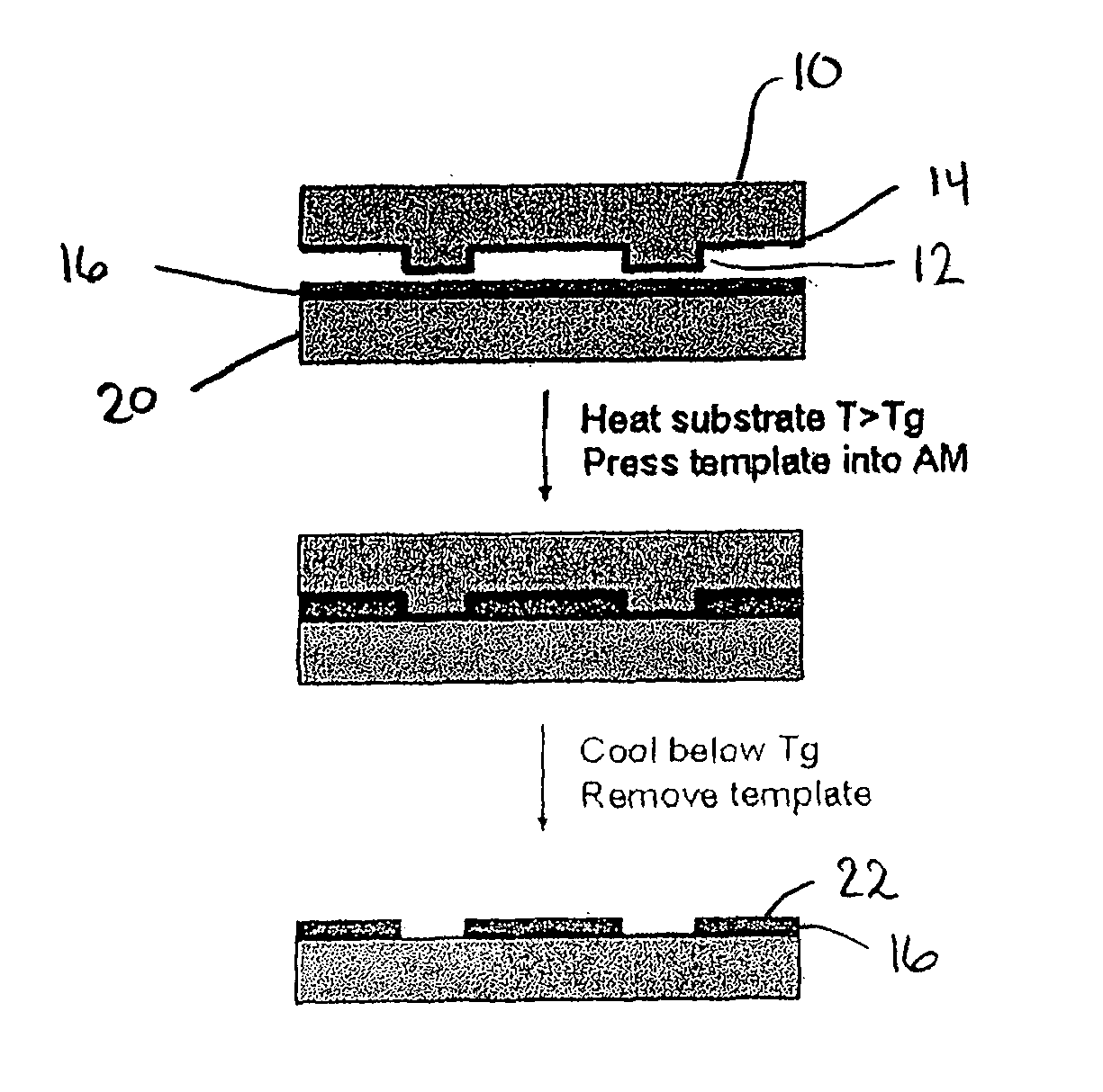
[0059]In one embodiment, the present invention relates generally to a method of imprinting microfeatures or nanofeatures into an amorphous metal alloy layer, the method comprising the steps of:[0060]a) heating an amorphous metal alloy layer to a temperature within a supercooled liquid region of the amorphous metal alloy to soften the amorphous metal alloy layer;[0061]b) transferring a pattern into the softened amorphous metal alloy layer; and[0062]c) cooling the amorphous metal alloy to a temperature below the super cooled liquid temperature region (which temperature is also below the glass transition temperature of the amorphous metal alloy) to resolidify the amorphous metal alloy layer.

[0063]In one embodiment of the invention, the step of transferring the pattern into the softened amorphous metal alloy layer comprises:[0064]a) pressing a mold having a desired pattern disposed thereon into the softened amorphous alloy layer to transfer the pattern into the amorphous softened metal ...


PUM

PropertyMeasurementUnit
glass transition temperatureaaaaaaaaaa
aspect ratioaaaaaaaaaa

Abstract

The present invention relates to materials, methods and apparatuses for performing imprint lithography using amorphous metallic materials. The amorphous metallic materials can be employed as imprint media and thermoplastic forming processes are applied during the pattern transfer procedure to produce micron scale and nanoscale patterns in the amorphous metallic layer. The pattern transfer is in the form of direct mask embossing or through a serial nano-indentation process. A rewriting process is also disclosed, which involves an erasing mechanism that is accomplished by means of a second thermoplastic forming process. The amorphous metallic materials may also be used directly as an embossing mold in imprint lithography to allow high volume imprint nano-manufacturing. This invention also comprises of a method of smoothening surfaces under the action of the surface tension alone.

Description

CROSS-REFERENCE TO RELATED APPLICATIONS[0001]The present application claims the benefit of U.S. Provisional Application Ser. Nos. 60 / 901,461 and 61 / 022,065, the subject matter of each of which is herein incorporated by reference in its entirety.FIELD OF THE INVENTION[0002]The present invention relates to improved techniques for nano-imprinting a pattern into an amorphous metal alloy substrate as well as erasing a pattern from the substrate.BACKGROUND OF THE INVENTION[0003]Bulk metallic glasses (BMGs), which are also known as bulk solidifying amorphous alloy compositions, are a class of amorphous metallic alloy materials that are regarded as prospective materials for a vast range of applications because of their superior properties such as high yield strength, large elastic strain limit, and high corrosion resistance.[0004]A unique property of BMG is that they have a super-cooled liquid region (SCLR), ΔTsc, which is a relative measure of the stability of the viscous liquid regime. Th...

Claims


Application Information

Patent Timeline
Patent Type & Authority Applications(United States)
IPC IPC(8): B32B3/30B22D23/00
CPCC21D6/04C22C45/00G11B3/705C22C45/001Y10T428/12389C22C45/02C22C45/04C21D2221/00C22C2200/02C22C45/003
Inventor SCHROERS, JANKUMAR, GOLDENTANG, HONGXING
Owner YALE UNIV
Why Eureka
Try Eureka