
Control device for machine tool

a control device and machine tool technology, applied in the direction of program control, total factory control, instruments, etc., can solve the problems of inability to deliver to a machining program, inability to prevent human errors, etc., and achieve the effect of preventing human errors in input and/or calculation by operators

Inactive Publication Date: 2017-08-03
MAKINO MILLING MASCH CO LTD
View PDF1 Cites 9 Cited by
  • Summary
  • Abstract
  • Description
  • Claims
  • Application Information

AI Technical Summary

Benefits of technology

The invention is a control device for a machine tool that improves the process of calculating machining conditions. It stores pre-calculated formulas for different types of calculations and parameters needed for those calculations. This prevents errors caused by operators who input or calculate data. The device displays the necessary parameters based on the selected calculation type, making the process easier and more accurate. Overall, the invention prevents errors and improves the efficiency of machine tool operations.

Problems solved by technology

Further, in the inventions of documents 1 and 2, the current coordinate of a machine tool cannot to be read as an input data, and the calculation results cannot be delivered to a machining program as arguments, and therefore human errors cannot be prevented.

Method used


Image

  • Control device for machine tool
  • Control device for machine tool
  • Control device for machine tool

Examples


Embodiment Construction

[0032]With reference to the attached drawings, a preferred embodiment of the invention will be described below.

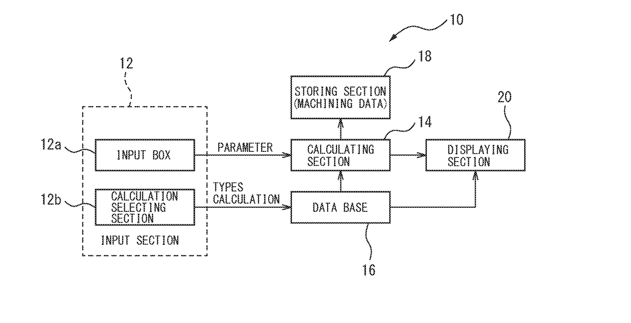
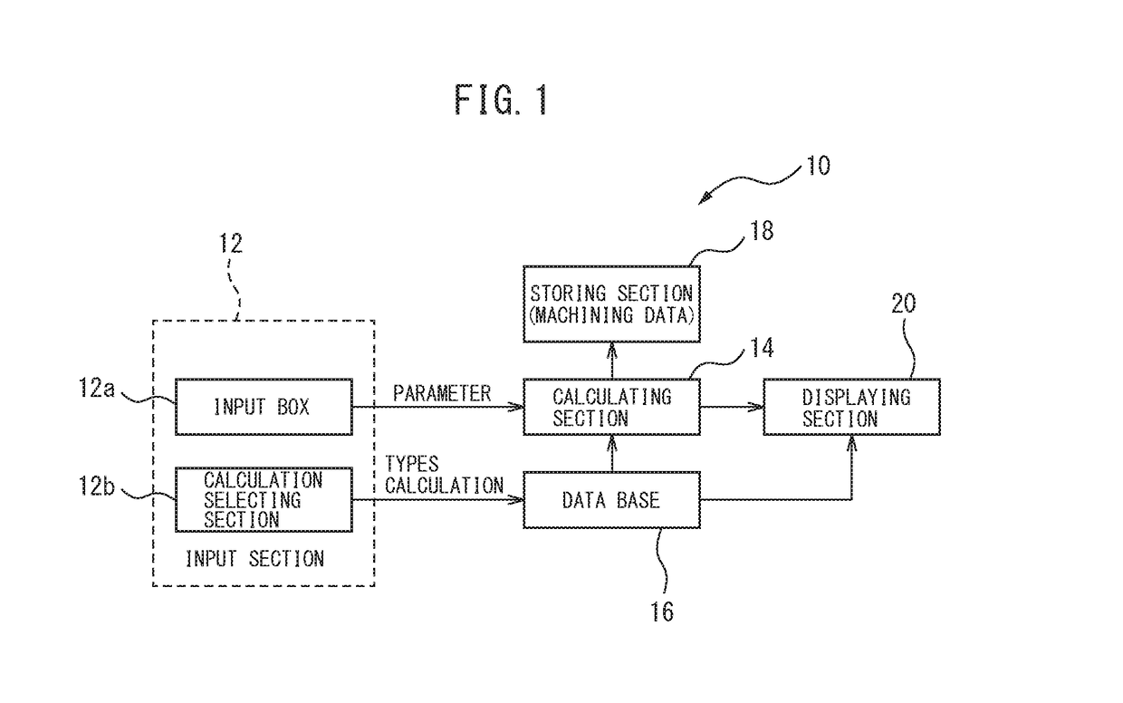
[0033]With reference to FIG. 1, which is a schematic block diagram of a control device of a machine tool according the a preferred embodiment of the invention, the control device 10 comprises as main parts an input section 12, a calculating section 14, a database 16, a storing section 18 and a displaying section 20.

[0034]The input section 12 is formed by a window displayed on the displaying section 20, which can be formed of a touch panel or the like, and as described below, includes an input box 12a and a calculation selecting section 12b formed by a drop down list. In the database 16, a various calculation formulas are stored in association with calculation types. Further, in the database 16, parameters such as the tool the diameter D, the tool length L, the number of teeth N, the feed per tooth fz, the feed rates F and the rotational speed S are stored in association wit...


PUM


Abstract

In order to make it possible for an operator of a machine tool to easily calculate machining conditions and prevent calculation errors and input errors by the operator, this control device for a machine tool, which machines a work piece on the basis of a machining program, is provided with: a database that stores calculation formulas corresponding to types of calculation, and types of parameters required to execute said calculation formulas; an input unit that selects a type of calculation; and a display unit that displays, on the basis of the type of calculation selected by the input unit, the parameter to be input.

Description

CROSS-REFERENCE TO RELATED APPLICATIONS[0001]This application is a U.S. National Stage patent application of International Patent Application No. PCT / JP2014 / 076228, filed on Sep. 30, 2014, which is hereby incorporated by reference in the present disclosure in its entirety.FIELD OF THE INVENTION[0002]The invention relates to a control device for a machine tool, allowing an operator of the machine tool to calculate the machining conditions easily whereby to prevent human errors in input and / or calculation by operators.BACKGROUND OF THE INVENTION[0003]The machining conditions, such as the feed rates of the feed devices and the rotational speed of the spindle of a machine tool are described in machining programs. However, in some cases, an operator actually must input the feed rates and the spindle rotation speed directly into an NC device at the site, e.g., a factory, or create or edit an NC program in the vicinity of a machine tool, based on the operator's experiences. The data to be ...

Claims


Application Information

Patent Timeline
IPC IPC(8): G05B19/409
CPCG05B19/409G05B2219/23258G05B2219/23472G05B19/40937G05B2219/36284Y02P90/02
Inventor KAWAI, RIEHEISHI, HIDEKIONO, KENICHIHOSHINO, YOSHIHIRO
Owner MAKINO MILLING MASCH CO LTD
Learn More