Arthroscopic devices and methods

a technology of arthroscopic devices and tissue, applied in the field of arthroscopic tissue cutting and removal devices, can solve the problems of joint failure, wear and tear, and adverse effects on patient health, and achieve the effect of improving the endoscopic viewing of the targeted treatment site, robust and economical connection

a technology of arthroscopic devices and tissue, applied in the field of arthroscopic tissue cutting and removal devices, can solve the problems of joint failure, wear and tear, and adverse effects on patient health, and achieve the effect of improving the endoscopic viewing of the targeted treatment site, robust and economical connection

US20170224368A1Active Publication Date: 2017-08-10RELIGN CORP

Image

  • Arthroscopic devices and methods
  • Arthroscopic devices and methods
  • Arthroscopic devices and methods

Examples


Embodiment Construction

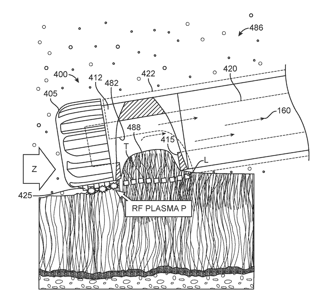
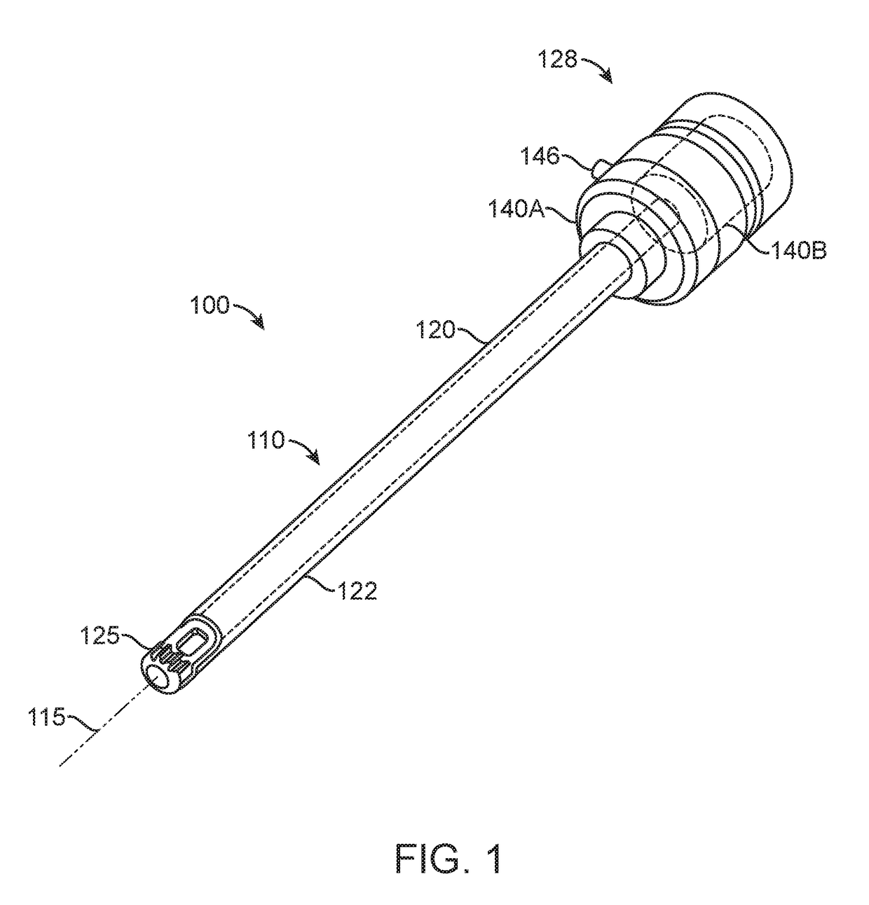
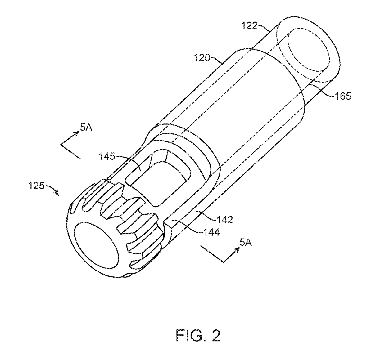
[0081]The present invention relates to bone cutting and removal devices and related methods of use. Several variations of the invention will now be described to provide an overall understanding of the principles of the form, function and methods of use of the devices disclosed herein. In general, the present disclosure provides for an arthroscopic cutter or burr assembly for cutting or abrading bone that is disposable and is configured for detachable coupling to a non-disposable handle and motor drive component. This description of the general principles of this invention is not meant to limit the inventive concepts in the appended claims.

[0082]In general, the present invention provides a high-speed rotating ceramic cutter or burr that is configured for use in many arthroscopic surgical applications, including but not limited to treating bone in shoulders, knees, hips, wrists, ankles and the spine. More in particular, the device includes a cutting member that is fabricated entirely ...


PUM


Abstract

A medical device includes an elongated sleeve having a longitudinal axis, a proximal end and a distal end. A cutting member having sharp edges formed from a wear-resistant ceramic material is carried at the distal end of the elongated sleeve. A motor drive is coupled to the proximal end of the elongated sleeve to rotate the sleeve at cutting member at high speed to cut bone and other hard tissue. An electrode is carried in a surface portion of ceramic cutting member for cautery or radiofrequency ablation of tissue when the sleeve and cutting member are is a stationary position.

Description

CROSS-REFERENCE TO RELATED APPLICATIONS[0001]This application claims the benefit of provisional application No. 62 / 291,249 (Attorney Docket No. 41879-714.101), filed on Feb. 4, 2016, and 62 / 324,236 (Attorney Docket No. 41879-722.101), filed on Apr. 18, 2016, the full disclosures of which are incorporated herein by reference.BACKGROUND OF THE INVENTION[0002]1. Field of the Invention[0003]This invention relates to arthroscopic tissue cutting and removal devices by which anatomical tissues may be cut and removed from a joint or other site. More specifically, this invention relates to instruments configured for cutting and removing tissue with a ceramic cutting member and / or electro surgically treating tissue with an electrode carried by the ceramic cutting member.[0004]2. Description of the Background Art[0005]In several surgical procedures including subacromial decompression, anterior cruciate ligament reconstruction involving notchplasty, and arthroscopic resection of the acromioclav...

Claims


Application Information

Patent Timeline
10 Aug 2017
Publication
US20170224368A1
IPC
A61B17/32; A61B17/16; A61B17/3205; A61B18/14
CPC
A61B17/32002; A61B18/1482; A61B2018/00595; A61B17/3205; A61B17/16; A61B17/1615; A61B17/1633; A61B2017/0088
Inventors
GERMAIN, AARON; KLEIN, KYLE