Medical elongated body and balloon catheter

a technology of elongated body and balloon catheter, which is applied in the direction of balloon catheter, coating, catheter, etc., can solve the problem of remaining difficult to sufficiently compensate for the deterioration of joining strength, and achieve the effect of improving the joining strength between the tube body and the distal member

Active Publication Date: 2017-08-10
TERUMO KK
View PDF3 Cites 0 Cited by
  • Summary
  • Abstract
  • Description
  • Claims
  • Application Information

AI Technical Summary

Benefits of technology

[0007]The medical elongated body and balloon catheter here thus improve the joining strength between the tube body and the distal member in a different respect.
[0010]When joining the tube body of the catheter main body and the distal member to each other in the medical elongated body described above, the inner layer of the tube body (of which fusing properties with respect to the distal member are excellent) is interposed between the outer layer and the distal member of the tube body. The tube body and the distal member are thus firmly joined to each other via the inner layer of the tube body, and therefore, the joining strength between the tube body and the distal member is improved.
[0011]When joining the tube body of the inner tube shaft and the distal member to each other in the balloon catheter described above, the inner layer of the tube body (of which fusing properties with respect to the distal member are excellent) is interposed between the outer layer and the distal member of the tube body. The tube body and the distal member are thus firmly joined to each other via the inner layer of the tube body, and therefore, the joining strength between the tube body and the distal member is improved.

Problems solved by technology

It remains difficult to sufficiently compensate for the deterioration of the joining strength caused by the combination of the material for forming the tube body and the material for forming the distal member by simply improving the physical joined structure between both of the tube body and the distal member in consideration of the arrangement relationship when joining the tube body and the distal member to each other.

Method used


Image

  • Medical elongated body and balloon catheter
  • Medical elongated body and balloon catheter
  • Medical elongated body and balloon catheter

Examples


first embodiment

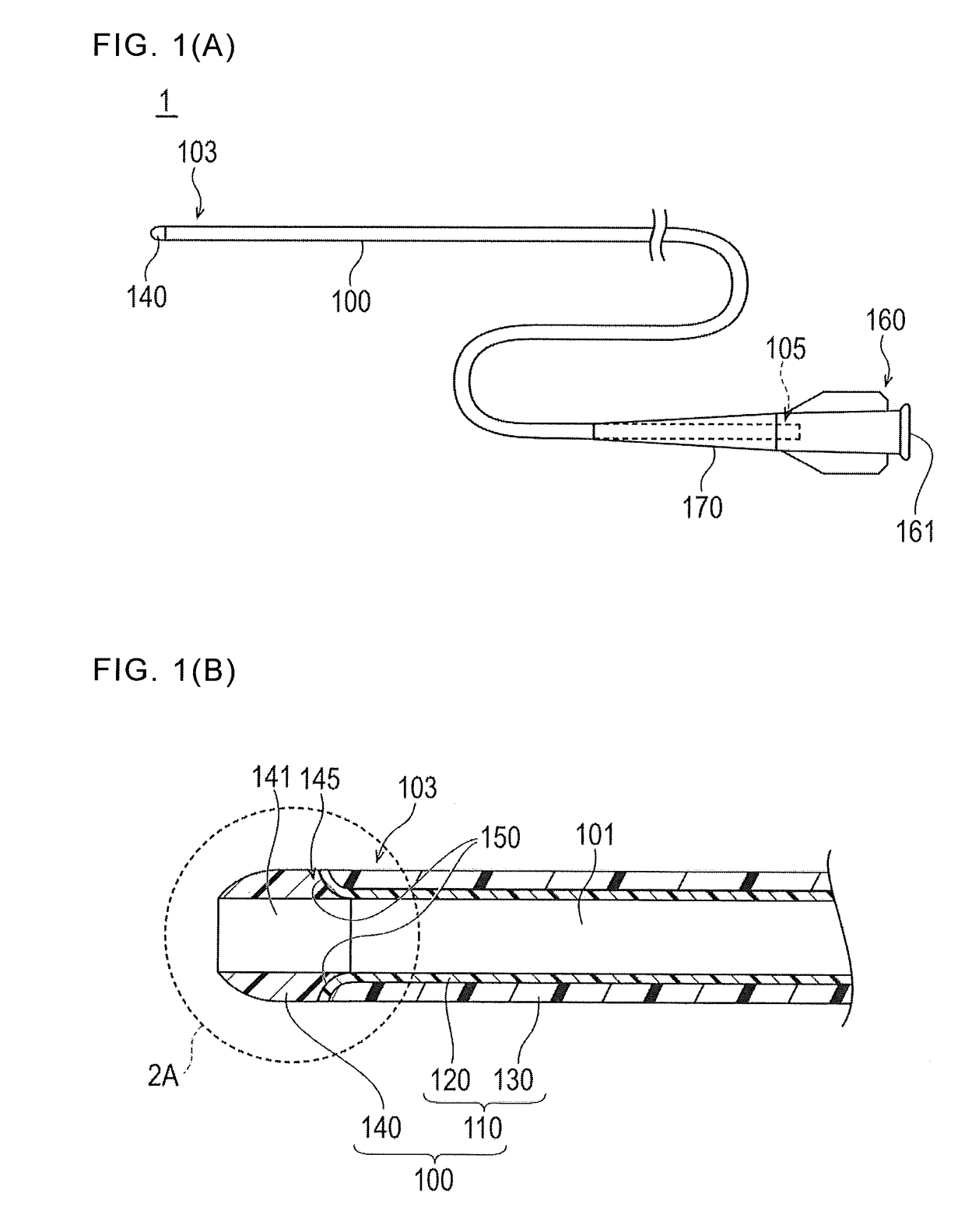
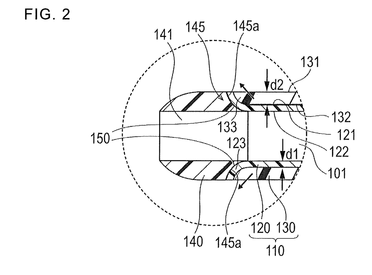
[0021]Hereinafter, a medical elongated body 1 according to a first embodiment will be described in reference to FIGS. 1(A) to 3. FIGS. 1(A), 1(B) and 2 are views showing configurations of each portion of the medical elongated body 1 and FIG. 3 is a view showing an example of a method for joining the tube body 110 and the distal member 140 of the medical elongated body 1. The dimensional ratios in each drawing may be exaggerated and / or different from the actual ratios for the convenience of description.

[0022]The medical elongated body 1 is a catheter for performing treatment, diagnosis, or the like after the medical elongated body 1 is inserted into blood vessels, bile ducts, the trachea, the esophagus, the urethra, or other biological lumens or lumens in a living body.

[0023]In the description below, the side (i.e., the left side of FIG. 1(A)) of the medical elongated body 1 that is inserted into a living body is referred to as the “distal side” or “distal end”, the side of the medic...

modification example

[0058]A medical elongated body 1 according to a modification example of the first embodiment is shown in FIG. 4.

[0059]In the embodiment illustrated in FIGS. 1(A)-2 described above, the inner layer 120 in the joint portion 150 is sandwiched between the outer layer 130 and the distal member 140 in the cross section taken along the axial direction of the tube body 110. In contrast, FIG. 4 illustrates a modification example with a non-intervention portion 155. The non-intervention portion 155 includes a portion in which the inner layer 120 is not interposed between the outer layer 130 and the distal member 140. Even when this non-intervention portion 155 is formed, it is possible to fuse the inner layer 120 directly to the distal member 140 if at least a part of the inner layer 120 is interposed between the outer layer 130 and the distal member 140. Accordingly, it remains possible to improve the joining strength between a tube body 110 and the distal member 140 even in the medical elon...

second embodiment

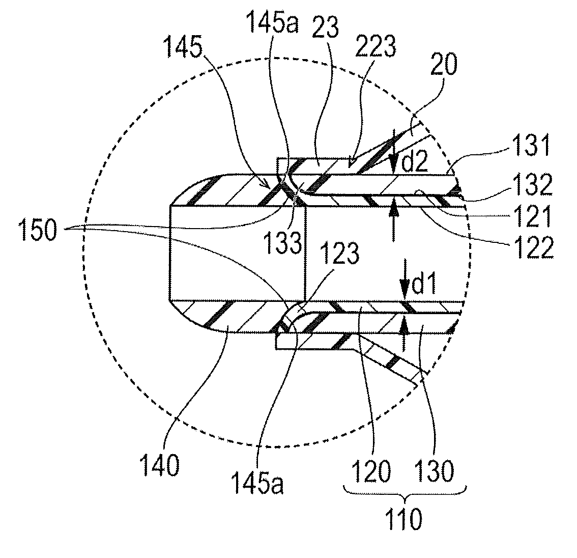
[0061]Next, a balloon catheter 2 embodiment as illustrated in FIGS. 5(A)-6(B) will be described. FIGS. 5(A)-6(B) are views illustrating the configurations of different portions of the balloon catheter 2.

[0062]The balloon catheter 2 is a medical device which treats a stenosed site (lesion area) by widening the stenosed site. The balloon catheter 2 widens the stenosed site by inserting an elongated shaft 200 into a biological organ and dilating a balloon 20 disposed on a distal side of the shaft 200 within the stenosed site.

[0063]The balloon catheter 2 illustrated in FIG. 5(A) is a balloon catheter for PTCA (percutaneous transluminal coronary angioplasty) expansion which is used for widening a stenosed site of the coronary artery. It is possible to, for example, use the balloon catheter 2 to treat and improve a stenosed site formed in other blood vessels, bile ducts, the trachea, the esophagus, other digestive tracts, the urethra, the lumen of the nose and ears, and other biological o...


PUM

PropertyMeasurementUnit
flexibleaaaaaaaaaa
sliding resistanceaaaaaaaaaa
thicknessaaaaaaaaaa

Abstract

A medical elongated body or a balloon catheter that include a catheter main body, a tubular body, and a distal member at a distal end of the tubular body. The distal member is more flexible than the tubular body. The distal end of the tubular body is joined to the distal member at a joint portion. The tubular body includes an outer layer and an inner layer disposed inside of the outer layer in the radial direction of the tubular body. The material of the inner layer possesses better fusing properties with respect to the distal member than the fusing properties of the outer layer material with respect to the distal member material. The inner layer is interposed between the distal member and the outer layer by extending between the distal member and the outer layer at the joint portion.

Description

CROSS-REFERENCES TO RELATED APPLICATIONS[0001]This application claims priority to Japanese Application No. 2016-024064 filed on Feb. 10, 2016, the entire content of which is incorporated herein by reference.TECHNICAL FIELD[0002]The present invention relates to a medical elongated body and a balloon catheter.BACKGROUND ART[0003]A medical elongated body including a catheter main body consisting of a hollow member in which a lumen is formed or a balloon catheter or the like including an inner tube shaft in which a guide wire lumen is formed may be used when performing various medical procedures in a biological organ of a living body. In general, the medical elongated body or inner tube shaft include an elongated tube body and a distal member disposed at a distal portion of the elongated tube body. In some cases, the distal member is formed of a material which is more flexible than the tube body material in order to prevent any damage to a biological lumen such as a blood vessel.[0004]T...

Claims


Application Information

Patent Timeline
Patent Type & Authority Applications(United States)
IPC IPC(8): A61M25/10A61L29/06A61M25/09A61L29/04A61M25/00A61M25/01
CPCA61M25/1025A61M25/1034A61M25/0097A61L29/06A61M25/09A61M25/104A61L29/041A61M25/0108A61M25/001A61M25/0045A61M25/0069A61M25/10A61M2025/0081A61M2025/1093
Inventor SUZUKI, KENTA
Owner TERUMO KK
Why Eureka
Try Eureka