Reduced power consumption electromagnetic lock

a technology of electromagnetic locks and power consumption, applied in the field of electromagnetic locks, can solve the problems of unnecessarily expend energy, system suffer from a number of significant drawbacks, waste of energy (electricity), etc., and achieve the effect of constant current flow through the windings

Active Publication Date: 2017-08-10
HANCHETT ENTRY SYST
View PDF13 Cites 29 Cited by
  • Summary
  • Abstract
  • Description
  • Claims
  • Application Information

AI Technical Summary

Benefits of technology

[0016]In accordance with another aspect of the invention, during the off-portion of the pulse width modulated duty cycle, a level of inductive current continues to flow through the magnetic core windings. The inductance associated with the windings when the current through the windings change (due to the “on / off” pulse-width modulated current to the windings) discharges stored energy contained in the windings thereby maintaining a constant current flow through the windings. During the on-portion of the duty cycle, the energy that was lost from the windings during the off-portion of the duty cycle is replenished, enabling the above-described constant current flow through the windings to be maintained.

Problems solved by technology

These systems suffer from a number of significant drawbacks.
For instance, a great deal of energy (electricity) is wasted while powering the door lock when the door is closed and no attempts are made to open the secured door.
Similarly, re-energizing the electromagnet after a fixed delay may unnecessarily expend energy.
For instance, if an authorized individual takes longer to pass through the doorway than the delay period, that portion of time in which the electromagnet is re-energized without the door being closed constitutes power waste.
In a dramatic example, should the door be propped open such power waste may be substantial.
This waste is not only detrimental to the environment, but also unnecessarily increases the electricity costs incurred by the door owner.

Method used


Image

  • Reduced power consumption electromagnetic lock
  • Reduced power consumption electromagnetic lock
  • Reduced power consumption electromagnetic lock

Examples


Embodiment Construction

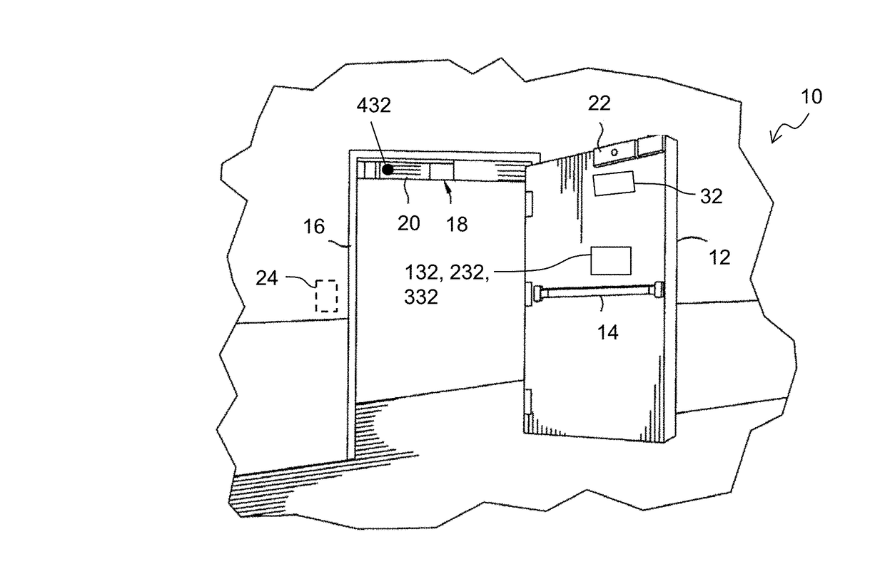
[0028]As used herein, the term “unauthorized attempt to open the door” shall mean a forceful attempt to open the door to gain unauthorized entry to an area secured by the door. The term “naturally occurring external forces” shall mean forces that may be applied to the door (such as wind forces or vibration) that may move the door from its closed position other than forces attributed to an unauthorized attempt to open the door. Referring to FIG. 1, in an electromagnetic door locking system 10 in accordance with the present invention, mounted to door frame 16 is an electromagnet assembly 18 including electromagnet 20. Door 12 is provided with an armature 22 for electromagnetically locking to electromagnet 20. In a secured setting, an authentication device 24, such as a keypad, swipe card reader, key fob reader or biometric sensor may be provided whereby the electromagnet 20 de-energizes only upon input of proper access credentials at authentication device 24, thereby releasing armatur...


PUM


Abstract

An energizable electromagnet of a door locking system is affixed to the door or the door frame for electromagnetically attracting an armature affixed to the other. A power control circuit is configured to selectively energize the electromagnet using a pulse-width modulated current cycle wherein two levels of magnetic force may be selectively applied to the system. A door position sensor is configured to provide a first communication signal to the power control circuit when the door is in a closed position. A second communication signal is provided when the door is not in the closed position. The electromagnet is energized at the lower level of magnetic force when the power control circuit receives the first communication signal and at the higher level of magnetic force only when an unauthorized attempt to open the door is initiated.

Description

CROSS-REFERENCE TO RELATED APPLICATIONS[0001]This application claims the benefit of U.S. patent application Ser. No. 62 / 293,185, filed Feb. 9, 2016, the contents of which are hereby incorporated by reference in its entirety.TECHNICAL FIELD[0002]The present invention relates to a locking system; more particularly, to an electromagnetic door locking system; and most particularly, to an electromagnetic door locking system having power saving features.BACKGROUND OF THE INVENTION[0003]Existing electromagnetic circuits employed within door locking systems constantly supply power to the electromagnet to keep the door locked. In the current art, the electromagnetic coil of the door locking system may include two windings to accommodate two levels of available voltage supplies in the field, as for example, a 12 volt DC supply or a 24 volt voltage supply. In order to provide the magnetic holding force needed to hold the door closed against an unauthorized opening, the two windings may be sele...

Claims


Application Information

Patent Timeline
Patent Type & Authority Applications(United States)
IPC IPC(8): E05C19/16G07C9/00E05B47/00
CPCE05C19/166E05B47/00G07C2009/00634E05B2047/0068G07C9/00174
Inventor DAVIS, BRETT L.SHAFFER, RANDALL
Owner HANCHETT ENTRY SYST
Why Eureka
Try Eureka