
Display device and electornic apparatus

a technology of electornic apparatus and display device, which is applied in the direction of optics, optical elements, instruments, etc., can solve the problems of difficulty in enhancing increasing power consumption, and achieve the effects of reducing the efficiency of light extraction, suppressing color mixture, and increasing the reflected component of external ligh

Active Publication Date: 2017-08-10
SONY CORP
View PDF10 Cites 6 Cited by
  • Summary
  • Abstract
  • Description
  • Claims
  • Application Information

AI Technical Summary

Benefits of technology

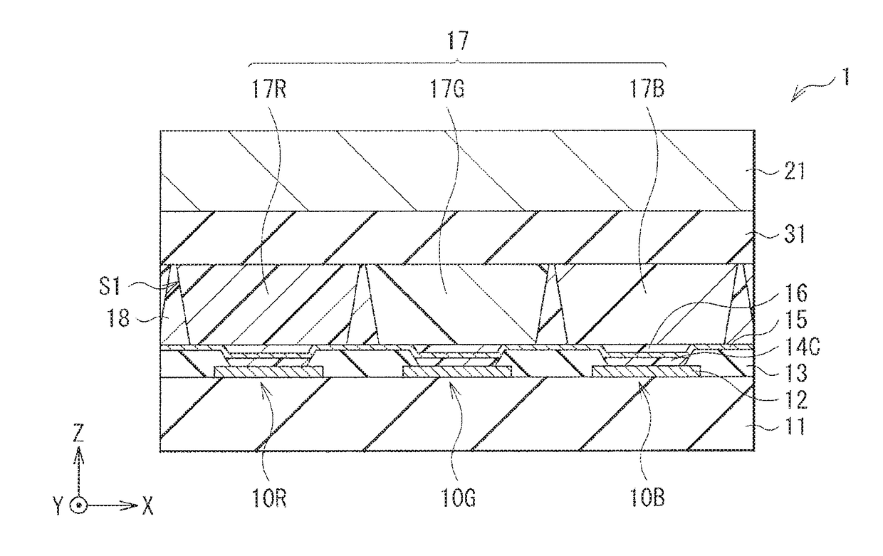
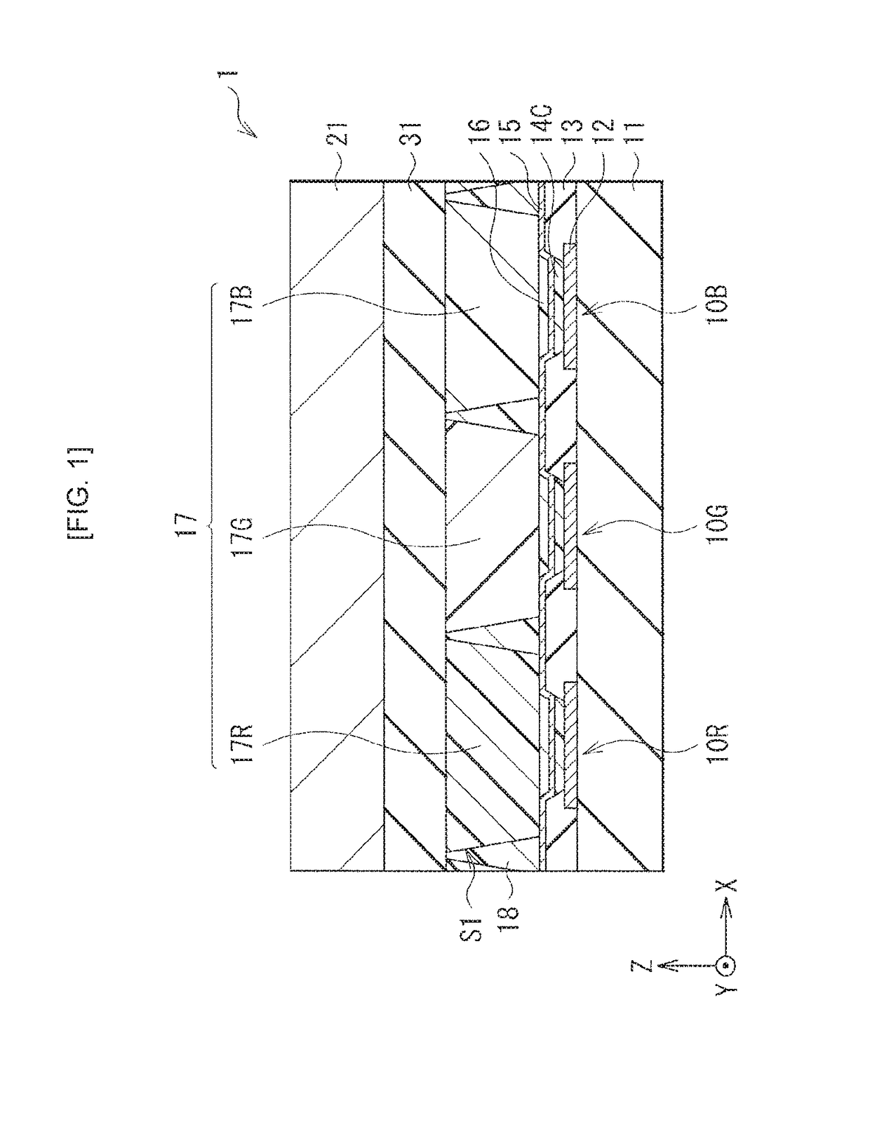
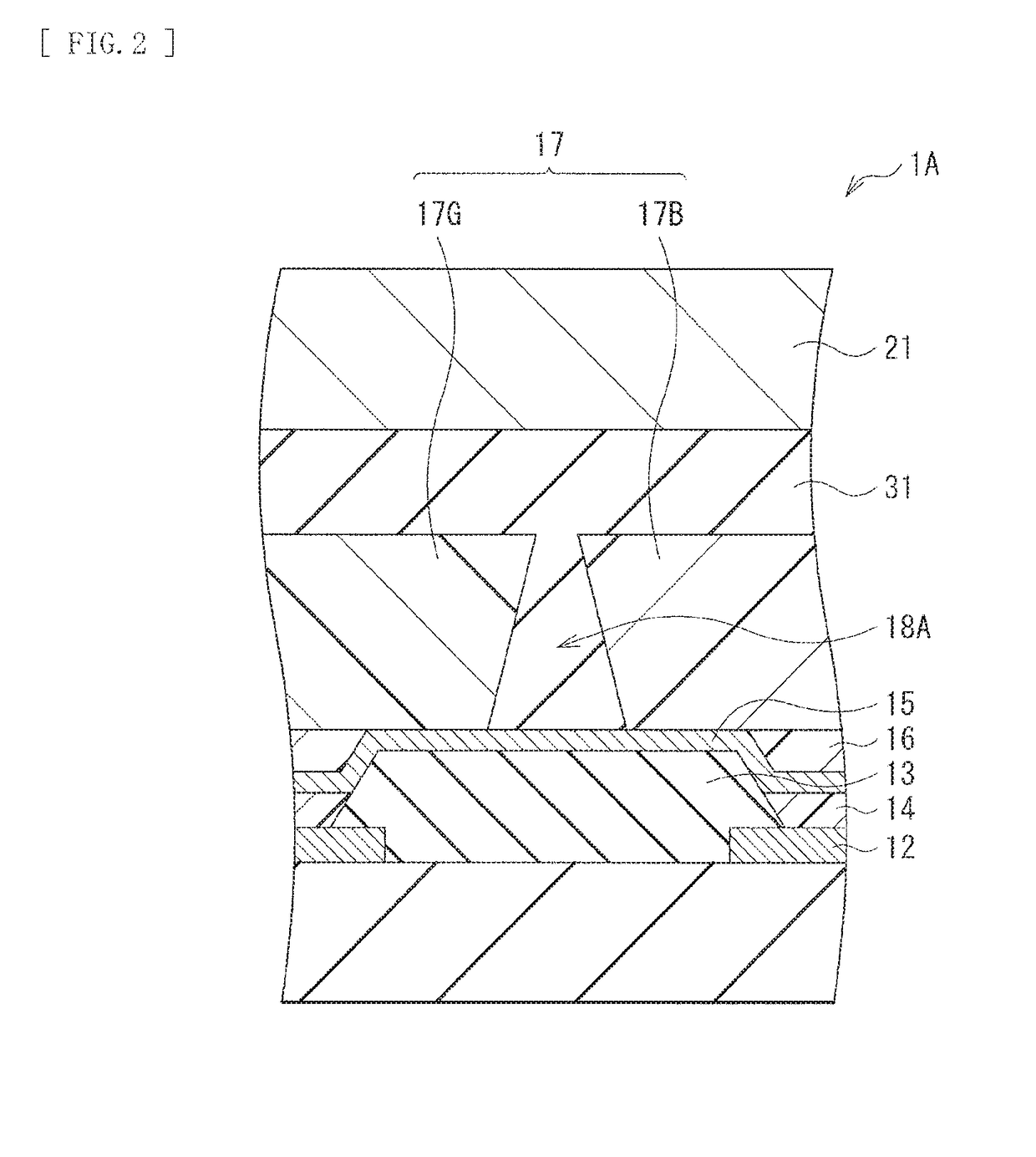
The patent is about a display device and electronic apparatus that can improve light extraction and prevent color mixing between pixels. It achieves this by disposing color elements over light emitting elements, with inclined planes on the edge faces of adjacent color elements. A reflector structure is also provided between the edge faces, which reflects the emission light towards the color elements. This leads to an enhancement of light extraction without the need for a black matrix and prevents the emission light from intruding into neighboring color elements. The patent proposes that these effects can be realized in various ways, and other effects can also be achieved.

Problems solved by technology

Such a display device may have a disadvantage that necessary current density becomes larger, causing an increase in power consumption.
Thus, it is difficult to enhance the efficiency of the light extraction while suppressing the color mixture.

Method used


Image

  • Display device and electornic apparatus
  • Display device and electornic apparatus
  • Display device and electornic apparatus

Examples


modification example

[2. Modification Example]

[0066]FIG. 10 illustrates a cross-sectional configuration of a display device (a display device 2) according to a modification example of the disclosure. The display device 2 may be different from the forgoing embodiment in that an edge face of a color filter 57R, 57G or 57B may have inclination in a forward taper, in which the edge face is adjacent to the color filter of another color. The color filters 57R, 57G and 57B are provided over the light emitting elements 10R, 10G and 10B. A gap is provided by inclined planes S1 in the forward taper. In the gap, provided is a reflector structure 58. The reflector structure 58 may have a similar configuration to those of the reflector structure 18 (18A, 18B, and 18C) in the forgoing embodiment. Thus, providing the inclined plane S2 in the forward taper at the edge face of the color filter 57R, 57G or 57B, in which the edge face is adjacent to the color filter of another color, makes it possible to produce similar e...

application examples

[3. Application Examples]

[0067]The display devices 1 and 2 as described in the forgoing embodiment and the modification example may be applied to display devices of electronic apparatuses in various fields that display an image or a picture on the basis of a picture signal inputted from outside or a picture signal generated inside. Examples may include a television set, a digital camera, a notebook personal computer, a mobile terminal device such as a mobile phone, and a video camera. In particular, the display devices 1 and 2 may be suitably applied to a medium-sized or small-sized display for mobile applications. Some examples are given in the following.

[0068]FIG. 11 illustrates an external appearance of a head mount display 200 according to an application example 1. The head mount display 200 may include a display unit 210 (the display device 1 or 2) and a mounting unit 220.

[0069]FIGS. 12A and 12B respectively illustrate external appearances of a front surface and a rear surface ...


PUM


Abstract

A display device of the disclosure includes a first substrate that includes light emitting elements and color elements for respective pixels, in which the color elements are provided over the light emitting elements. The color elements include: a color element of one color including a first edge face; a color element of another color including a second edge face, in which the second edge face is adjacent to the first edge face, and at least the first edge face and the second edge face each have inclination; and a reflector structure provided in a gap formed by the inclination.

Description

TECHNICAL FIELD[0001]The disclosure relates to a display device that emits light with utilization of an organic electroluminescence (EL) phenomenon, and an electronic apparatus including the display device.BACKGROUND ART[0002]In a display device utilizing spontaneous light emitting elements such as organic EL elements, there has been pursuit of suppression of color mixture, enhanced efficiency of light emission, and longer drive lifetime. In a general display device, light emission elements may be provided on one of a pair of substrates, whereas a light-shielding black matrix may be provided on another of the pair of substrates. This allows for the suppression of the color mixture between adjacent pixels, but there are disadvantages such as an increase in a reflected component of external light and lowered efficiency of light extraction.[0003]PTL 1 therefore discloses, for example, a so-called on-chip lens (OCL) structure, for purpose of enhancement in the efficiency of the light ex...

Claims


Application Information

Patent Timeline
Patent Type & Authority Applications(United States)
IPC IPC(8): H01L27/32G02B27/01H01L51/50
CPCG02B27/017H05B33/24H01L51/50H01L27/32G02B5/20G02B5/201G02B2027/0112G02B27/0172H10K59/38H10K59/878H10K59/00H10K50/00H10K50/856
Inventor SUZUKI, MASAKI
Owner SONY CORP
Learn More