
Thin glass film composite web with reinforcing strips

a composite web and thin glass film technology, applied in the field of thin glass film composite webs, can solve the problems of increasing the risk of web cracks, difficult winding of thin glass film onto a roll, and high bending stiffness of thin glass film, and achieves favorable wounding, reduced bending stiffness, and high bending stiffness

Inactive Publication Date: 2017-08-17
TESA SE
View PDF4 Cites 11 Cited by
  • Summary
  • Abstract
  • Description
  • Claims
  • Application Information

AI Technical Summary

Benefits of technology

This patent is about a new adhesive for protective films on thin glass films. The adhesive is made with a special silane that increases the adhesion to glass and improves the stability of the adhesive to sunlight. The adhesive can be applied to the glass film before adhesion or added to the adhesive itself. The silane used in the adhesive helps to bridge microcracks on the glass surface, making it more durable and resistant to damage. The adhesive can also be made reversible, preventing any increase in adhesion to the glass film when the protective film is removed. The technical effect of this patent is to provide a more robust and protective film for thin glass films.

Problems solved by technology

In the effort to achieve sufficient useful life and functioning of optoelectronic devices in the area of inorganic and organic optoelectronics, and particularly in organic optoelectronics, protection of the components contained therein from permeates is to be seen as a particular technical challenge.
However, the border makes it more difficult to wind the thin glass film onto a roll, because on the one hand, this thickening allows only a small bending radius to be achieved, and on the other hand, the layers do not lie against one another in planar fashion.
In particular, in lateral web guidance of the thin glass film in a roll-to-roll process, particularly strong forces act on the edge, increasing the risk of web cracks.
However, the thin glass film is highly sensitive, and damage may occur, originating in particular from the glass edge of the thin glass film, especially when this glass edge has been cut.
A drawback of the glass coating is that it has an elastic modulus that is less than that of glass, and it therefore yields to tensile loads in the longitudinal direction of the thin glass film, so that the load is transferred directly to the edge of the thin glass film.
Moreover, reinforcing materials in the form of polymer or glass fibers are applied along the entire width of the glass coating, causing its overall flexibility to decrease.
The drawback in this case as well is that the polymer layer has a significantly lower elastic modulus than that of the thin glass film and therefore yields to tensile stress at the edge of the thin glass film, causing the stress to be transferred to the edge of the glass.
However, the coating is of a homogeneous material, and it is extremely thin at the edge, making it incapable of absorbing the tensile forces generated at the edge of the thin glass film during web guidance.
A drawback in this case as well is that the flexible polymeric carrier film has a significantly lower elastic modulus than glass, and therefore yields to a tensile stress at the edge of the thin glass film, with the result that the stress is transferred to the edge of the glass, where it can lead to crack formation.
The protective film is not suitable for protecting the edge by absorbing tensile forces acting from the edge.
A drawback is that because of the high tensile strength of the entire reinforcing layer, the resulting composite is extremely rigid, i.e., the flexibility of the composite material is significantly reduced compared to the pure glass film.

Method used


Image

  • Thin glass film composite web with reinforcing strips
  • Thin glass film composite web with reinforcing strips
  • Thin glass film composite web with reinforcing strips

Examples


Embodiment Construction

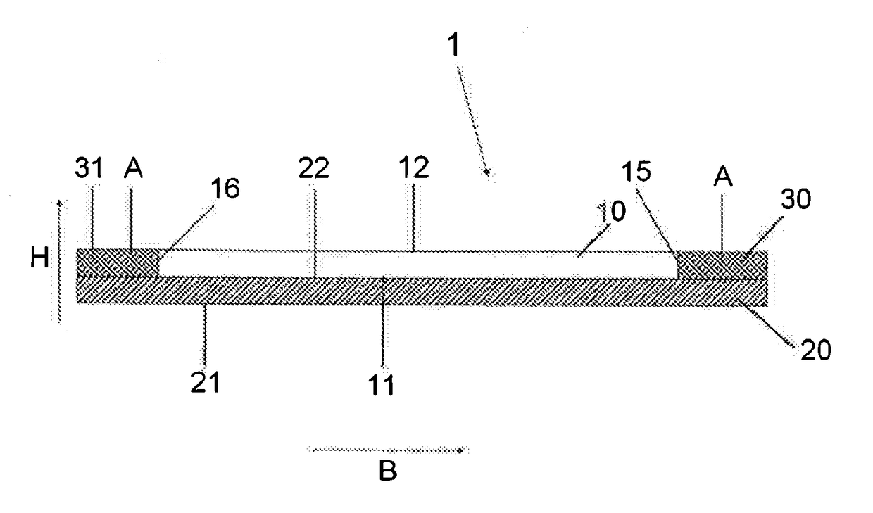
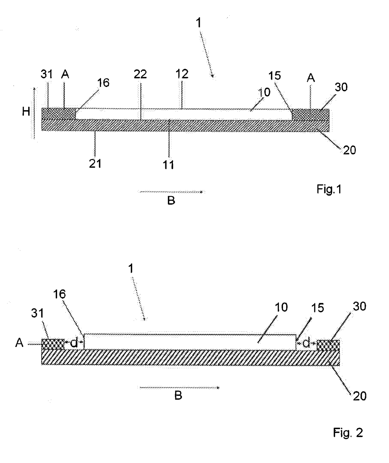
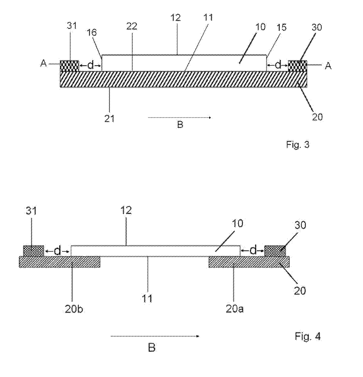
[0029]First, a film web is understood to be a sheetlike structure whose dimensions in one spatial direction, i.e. height or thickness, are significantly smaller than in the other two spatial directions. The main extension is defined by length and width. In a film web, moreover, width and thickness are specified. As a rule, however, the length of the film is not specifically defined. The length of the film web is ordinarily at least 10 times greater than the width. The film web can have a simple continuous configuration, or it may also be interrupted. It can consist of a single material or areas of different materials, but can either have a constant thickness over its entire surface area or have areas of different thicknesses. The film web can consist of one or a plurality of layers that are arranged in congruent fashion, or may have an at least partially non-overlapping configuration.

[0030]A thin glass film web in understood to refer to a film web having a height of 10 to 200 μm, pr...


PUM

PropertyMeasurementUnit
elastic modulusaaaaaaaaaa
thicknessaaaaaaaaaa
thicknessaaaaaaaaaa

Abstract

A thin glass film composite web comprising a thin glass film web (10) with a first surface (11), and a second surface (12), and two edges (15, 16) which run in the longitudinal direction (L) and comprising a protective film web (20) made of a first material, said protective film web extending along at least one part of the first surface (11), at least one reinforcing strip (30, 31) made of a second material which differs from the first material, said reinforcing strip running along at least one of the two edges (15, 16), the protective film web and the reinforcing strip being connected to each other such that the two can together be applied onto the thin glass web, and the at least one reinforcing strip (30, 31) having a greater relative tensile strength than the thin glass film web (10).

Description

[0001]This application is a 371 of PCT / EP2015 / 071498, filed Sep. 18, 2015, which claims foreign priority benefit under 35 U.S.C. §119 of the German Patent Application No. 10 2014 221 245.6 filed Oct. 20, 2014, the disclosures of which patent applications are incorporated herein by reference.BACKGROUND OF THE INVENTION[0002]The invention concerns a thin glass film composite web according to the generic concept of claim 1 and a method for the storage of thin glass film webs.[0003]Optoelectronic devices are being used with increasing frequency in commercial products or will soon be introduced onto the market. Such devices comprise inorganic or organic electronic structures such as organic, organometallic, or polymeric semiconductors or combinations thereof. Depending on the desired application, the corresponding products have a stiff or flexible configuration, and there is an increasing demand for flexible devices. The production of such devices is often carried out by printing process...

Claims


Application Information

Patent Timeline
Patent Type & Authority Applications(United States)
IPC IPC(8): B32B3/08B32B7/06B32B17/06H01L51/00B32B7/12H10K99/00
CPCB32B3/085H01L51/0097B32B7/12B32B17/064B32B2457/00B32B2307/54B32B2307/51B32B2307/7246B32B7/06B32B17/10018B32B17/10366H10K77/111Y02E10/549B32B3/08B32B17/10
Inventor KEITE-TELGENBUSCHER, KLAUSROMPF, JULIABENDEICH, MANUEL
Owner TESA SE
Learn More