
Rotary braiding machine

a rotary braiding machine and rotary technology, applied in the direction of connecting rods, shafts and bearings, paper and other directions, can solve the problems of difficult and/or impossible to make the small timing adjustments that are necessary for the efficient operation of the machine, and the rotary braiding machines known in the art are overly complex and complicated, and achieve the effect of faster and more efficient braiding

Active Publication Date: 2017-08-17
KARG CORP
View PDF0 Cites 29 Cited by
  • Summary
  • Abstract
  • Description
  • Claims
  • Application Information

AI Technical Summary

Benefits of technology

The present invention provides a braiding machine with an improved actuator arm mechanism that is simpler and more efficient than conventional rotary braiding systems. It allows for faster and more accurate braiding by controlling the length of the actuator arm mechanism and adjusting the timing of the machine's transfer arm. This results in faster production times and better quality products.

Problems solved by technology

There are a number of significant drawbacks with the rotary braiding machines known in the art, particularly when used to braid metal strands.
The rotary braiding machines known in the art are overly complex and complicated.
This complexity makes it difficult to keep the machines properly adjusted so they can be operated at higher speeds while maintaining high quality braids.
Moreover, many prior art designs make it difficult and / or impossible to make the small timing adjustments that are necessary for the machine to operate efficiently, particularly, at higher speeds.

Method used


Image

  • Rotary braiding machine
  • Rotary braiding machine
  • Rotary braiding machine

Examples


Embodiment Construction

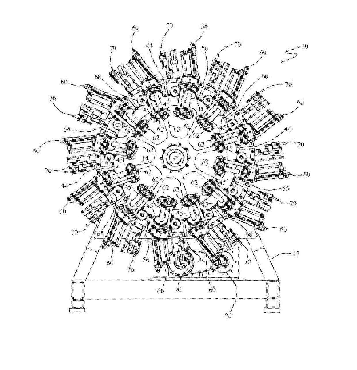
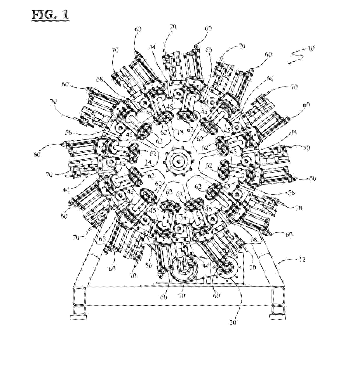
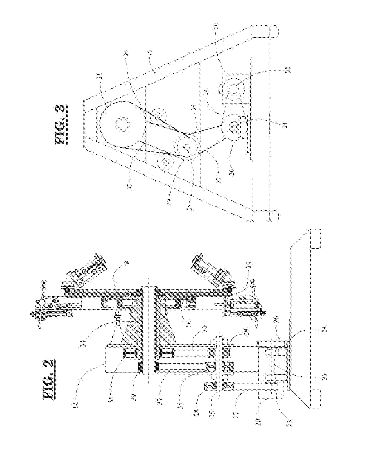
[0030]In one or more aspect, the present invention is directed to a rotary braiding machine capable of braiding wire around a cable, hose, mandrel, or other similar item, having an improved actuator arm mechanism, track design, and drive mechanism that is simpler and faster than conventionally available rotary braiding systems. In various embodiments, the rotary braiding machines of the present invention are particularly well suited to braiding strands made from sharp and / or abrasive material such as steel wire, spring steel, hard stainless steel, soft stainless steel, plain copper, tinned-copper, gold-plated copper, aluminum, nickel, monel, or bronze, but may also be used for textile braiding.

[0031]In general outline, rotary braiding system including those of the present invention includes two sets of carriers, each containing a bobbin holding the wire or other material to be braided, that are driven in opposite directions to form the desired braid around a cable, hose, mandrel, or...


PUM


Abstract

In one aspect, various embodiments of the present invention are directed to a rotary braiding machine capable of braiding wire around a cable, hose, mandrel, or other similar item, having an improved actuator arm mechanism that is simpler than those found in conventionally available rotary braiding systems and includes a mechanism for fine-tuning of the dwell timing of the transfer arms. In another aspect, one or more embodiment of the present invention is directed to a method for controlling the dwell timing of a transfer arm in a rotary braiding machine by adjusting the length of the actuator arm mechanism.

Description

FIELD OF THE INVENTION[0001]In one or more embodiments, the present invention relates to a rotary braiding machine. In certain embodiments, the present invention relates to a rotary braiding machine for braiding wire having an improved actuator arm mechanism.BACKGROUND OF THE INVENTION[0002]Rotary braiding machines are well known in the art and have been used to, among other things, braid strands of materials such as steel, stainless steel, bronze, polyester, nylon, arramed, carbon fibers and similar materials around substrates such as hoses or cables and have been of particular used in forming pressure resistant hydraulic hose. In various configurations, these rotary braiding machines feature two sets of bobbin carriers rotating in opposite directions along the same axis and the strands paying out from one set of bobbin carriers are moved around one or more of the other set of bobbin carriers, to form a braid.[0003]There are a number of significant drawbacks with the rotary braidin...

Claims


Application Information

Patent Timeline
IPC IPC(8): D04C3/42
CPCD04C3/42F16C7/06
Inventor KROCZYNSKI, MARKKARG, MICHAEL
Owner KARG CORP
Learn More