
Drilling rig and method of use

a drilling rig and rig body technology, applied in the direction of drilling rods, drilling pipes, lifting devices, etc., can solve the problems of increasing the amount of time that the drilling equipment needs to be transported between drilling sites, difficulty in transportation of equipment, and high cost of transportation of drilling equipment, so as to achieve the effect of easy and less expensive transportation and assembly

Active Publication Date: 2017-08-17
PIONEER ENERGY SERVICES
View PDF2 Cites 8 Cited by
  • Summary
  • Abstract
  • Description
  • Claims
  • Application Information

AI Technical Summary

Benefits of technology

The present invention is an improved system for assembling and disassembling drilling equipment at oil and gas well sites. The system has a simplified structure and is designed to reduce the number of loads needed for transport and assembly / disassembly. The structure includes a substructure with bracing that maintains its integrity using a telescoping tension link and two vertical cylinders. This bracing also allows for a reduced transport weight and the integration of a commercial walking system, reducing the number of transport loads required. The method may also include using a boost cylinder to assist in raising the floor of the substructure while rotating the screw jack. Overall, the system simplifies the process of assembling and disassembling drilling equipment, reducing the time and effort required.

Problems solved by technology

Primary economic and safety concern related to land-based reserve development of oil and gas reserves is the expense of transporting and setting up drilling equipment at the well sites.
Conventional drilling equipment for drilling oil and gas wells is heavy and bulky, making transportation of the equipment difficult.
Many remote sites lack adequate road systems for transporting heavy equipment, increasing the amount of time that the drilling equipment needs for transportation between drilling sites.
Logistic issues associated with transporting drilling equipment not only increases the cost of transportation, but increases the capital cost of an energy exploration and development project.
For instance, conventional drilling equipment is an expensive capital investment that remains unused during transportation.
Further, the workers that operate the drilling equipment are generally not engaged in their primary job function during transportation times. Thus, extended periods of time used to transport drilling equipment can drastically increase the overhead associated with a given well operation.
Moving extremely heavy loads has generally been a complicated task because of the large forces involved in lifting and transporting the heavy loads.
However, this break-down and subsequent reassembly process can be very time consuming, especially when a heavy load is only to be moved a small distance, or needs to be repositioned.
Drilling has inherent risks and hazards, and these are increased by transportation of the drilling equipment over significant distances.
Safety considerations can shut down drilling operations if, for instance, essential drilling equipment becomes impaired or inoperable, or is just plain missing.
When the drilling equipment is transported over extensive distances, essential equipment can easily be forgotten or misplaced.

Method used


Image

  • Drilling rig and method of use
  • Drilling rig and method of use
  • Drilling rig and method of use

Examples


Embodiment Construction

[0069]The present invention relates to the field of drilling wells, and more particularly, to an improved system that reduces the number of loads and simplifies assembling and disassembling drilling equipment at oil and gas land-based well sites.

Substructure

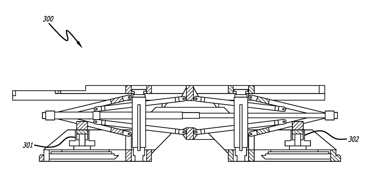
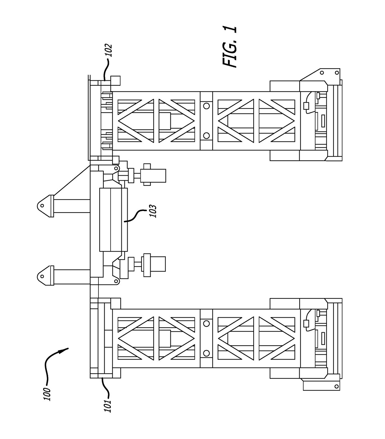
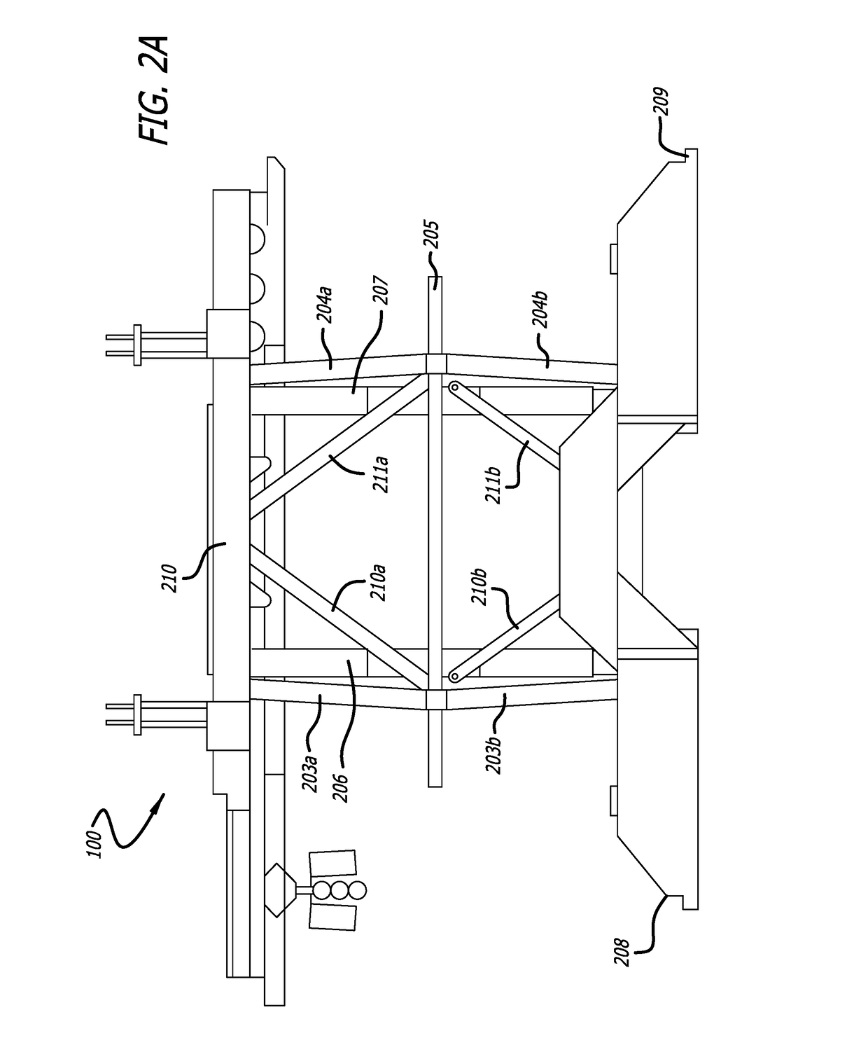
[0070]FIG. 1 illustrates a substructure 100 that includes two side boxes 101, 102 and a center-steel section 103. Referring to FIGS. 2A-2B, the substructure 100 of the present invention is also shown. FIG. 2A shows substructure 100 in its operating position (right side elevation view of substructure 100 shown in FIG. 1). Side boxes 101, 102 (shown in FIG. 1 and hidden in the right side elevation view of FIG. 2A) are maintained in a level position by support arms and bracing (upper support arm 203a, 204a, lower support arm 203b, 204b, upper support bracing 210a, 211a, and lower support bracing 210b, 211b) that are in a scissor jack (or grand plié) style bracing. The support arms (203a, 203b, 204a, 204b) and braces (210a, 210b, 211...


PUM


Abstract

An improved system and method for bracing, transporting, assembling, and disassembly of drilling equipment at oil and gas land-based well sites. The system has a substructure with side boxes support bracing that are in a scissor jack (or grand plié) style bracing with telescoping tension link(s), linking pins, and vertical hydraulic cylinders. These linking pins are set after raising the substructure and secure the telescoping tension link, support arms, and support bracing in place to maintain the integrity of the substructure. Alternatively the system has a substructure with side boxes support bracing that are in a scissor jack (or grand plié) style bracing with screw jacks and a means of stabilization during substructure raising. The substructure bracing reduces the overall length, reduces the upper and lower box spans, and balances the raising loads, subsequently lowering the transport weight of the side box such that a commercial walking system may be integrated into the side box and remain there during transport while maximizing the operating drill floor height while minimizing the transport height.

Description

CROSS-REFERENCE TO RELATED PATENT APPLICATIONS[0001]This application claims priority to: provisional United States Patent Application Ser. No. 62 / 035,629, filed on Aug. 11, 2014, entitled “Drill Rig And Method Of Use,” which provisional patent application is commonly assigned to the Assignee of the present invention and is hereby incorporated herein by reference in its entirety for all purposes.TECHNICAL FIELD[0002]The present invention relates to the field of drilling wells, and more particularly, to an improved system and method for transporting and assembling drilling equipment at oil and gas land-based well sites.BACKGROUND[0003]The present invention relates to a drilling rig and associated method of use, including transportation, assembly, and operational benefits. Primary economic and safety concern related to land-based reserve development of oil and gas reserves is the expense of transporting and setting up drilling equipment at the well sites. Conventional drilling equipmen...

Claims


Application Information

Patent Timeline
IPC IPC(8): E21B15/00B66F7/06B66F7/12B66F7/14E21B19/15E04H12/34
CPCE21B15/00E21B15/003E21B19/15E04H12/345B66F2700/05B66F7/14B66F7/065B66F7/0608B66F7/12E21B7/02
Inventor PRICE, CHRISTOPHERTARRENT, D. JARRETTARMBRUSTER, DAVIDORR, WILSONMOORE, MARC
Owner PIONEER ENERGY SERVICES
Learn More