Floating wave energy conversion island platforms

a technology of floating wave energy and platform, which is applied in the field of platforms, can solve the problems of high cost of component and implementation, high risk of damage caused by high waves, tsunami, typhoon, etc., and achieves the effects of ensuring the safety of the platform, reducing the risk of environmental impact and sea risks, and being easy to move into pla

Inactive Publication Date: 2017-08-17
NOIA GIAMPAOLO FRANCESCO
View PDF0 Cites 16 Cited by
  • Summary
  • Abstract
  • Description
  • Claims
  • Application Information

AI Technical Summary

Benefits of technology

[0013]In an embodiment, the safety of the platform can be assured by its very low center of gravity created by the location of the fixed and variable ballasts. If additional weight or floatation is desired, auxiliary cylinders can be attached externally to the load-bearing columns. The platform being a semi floating and not bound to the seabed is free from problems associated with any tides, typhoons, or tsunamis. The power cables and pipes that connect the island to the seabed, can have sufficient slack to absorb a significant amount of variation in its position along all three axes. Safety systems required of all sailing vessels including; anti-collision radars, lighting, life boats, radios, emergency location transmitter, helipad, and personal safety gear are part of the island platform's standard equipment. A free telemedicine service is also provided for the best assistance to personnel in case of need.
[0014]The present invention overcomes the problems listed above by providing a marine platform which is able to exploit the full range of wave motion including its movement in the rising phase, using the principle of Archimedes, and in its falling stage using the forces of gravity. The present invention does not require the use of a costly anchoring solution at a fixed location on the seabed or static infrastructure on the coas

Problems solved by technology

Wave Energy Conversion systems with submerged components, compared with the others, may have a relatively low environmental impact, but component and implementation costs are higher due to having to securely anchor them to the seabed in the open sea.
Traditional systems with floating devices, in turn, have similar anchoring challenges along with the risk of damage caused by high waves, storms, tsunami, and typhoons.
These have the potential to dest

Method used


Image

  • Floating wave energy conversion island platforms
  • Floating wave energy conversion island platforms
  • Floating wave energy conversion island platforms

Examples


Embodiment Construction

[0024]Referring to the drawings a description will be given of the embodiments of the present invention.

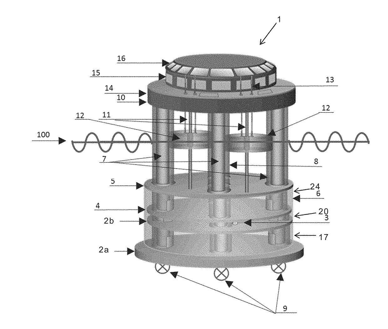
[0025]In FIG. 1, an outline of the semi-floating structure of the island platform 1 is presented with respect to sea level 100 with the submerged, partially submerged, and emerged sections identified and described as follow.

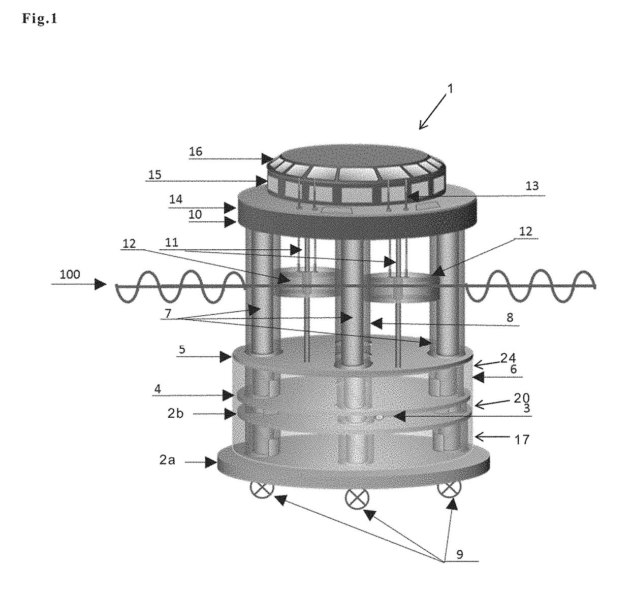
[0026]The island platform 1 has a structure in which a fixed ballast 2a, a variable ballast chamber 17, a gyroscope chamber 20 and one or more production chambers 24 are stacked from the base in the submerged section. The submerged section is also formed by large circular disks constructed of reinforced concrete or similar construction material which forms fixed ballast 2a, the variable water ballast chamber ceiling 2b, gyroscope 3, gyroscope chamber ceiling 4, and production chamber ceiling 5. The variable water ballast chamber ceiling 2b defines the top side of the variable ballast chamber 17 formed on the fixed ballast 2a. The chambers 17, 20 and 24 each are...


PUM


Abstract

A platform for exploiting the energy of waves operating in a marine environment and floating on the sea is disclosed. This comprises a submerged portion existing below a sea surface, an emerged portion existing above the sea surface, and a partially submerged wave power transfer mechanism portion including the sea surface and coupling the submerged portion and the emerged portion.

Description

BACKGROUND OF INVENTION[0001]The present invention relates to a platform, and in particular to an island platform for marine use capable of self-leveling, self-propelling, self-stabilizing, self-positioning and remotely controlled by radio from a virtual dashboard for production of electricity, drinking water, and other products using double action wave power converter.[0002]A number of techniques have been developed over the past century which have attempted to harness energy stored in sea waves around the world, and cost effectively convert this stored energy into a low cost renewable energy. These wave energy conversion techniques can be divided into three very general classes that include submerged, floating, and so-called oscillating water column types. The first two types primarily exploit the Principle of Archimedes. In the first case a hollow cylinder is anchored to the bottom of the sea and moves vertically taking advantage of the change of hydrostatic pressure from the pas...

Claims


Application Information

Patent Timeline
IPC IPC(8): F03B13/20B63B35/44C25B1/04H02K7/06C02F1/58E02B9/08H02K7/18
CPCC02F2103/08C02F2201/008C02F2201/009F03B13/20E02B9/08B63B2035/4466H02K7/1853H02K7/06C02F1/58C25B1/04B63B35/44F03B13/186B63B2035/4453B63B2035/446F05B2240/40F05B2240/93F05B2250/141F05B2270/18F05B2210/11Y02E10/30Y02E60/36F05B2250/44F03B13/16
Inventor NOIA, GIAMPAOLO FRANCESCO
Owner NOIA GIAMPAOLO FRANCESCO
Why Eureka
Try Eureka