X-ray source and system comprising an x-ray source

a technology of x-ray source and x-ray source, which is applied in the field of x-ray source, can solve the problems of reducing the overall efficiency of such a prior art arrangement and x-rays generated immediately, and achieves the effect of cost-effective operation of x-ray source and small energy consumption

Active Publication Date: 2017-08-17
PUREFIZE TECH AB
View PDF25 Cites 3 Cited by
  • Summary
  • Abstract
  • Description
  • Claims
  • Application Information

AI Technical Summary

Benefits of technology

[0018]Preferably, the x-ray source is configured to be connected to a controllable high voltage source for providing the above mentioned potential difference between the cathode and the anode. The high voltage source is electrically connected to the anode and the cathode and preferably configured to deliver a high voltage between (at least) 4-20 kV. Advantageously, the x-ray source may be adapted for generating a spectrum for the x-radiation up to approximately 20 keV when providing a current of as low as 1 mA. Accordingly, a suitable x-ray source may be provided with only small energy consumption, thus making the operation of the x-ray source cost efficient.
[0019]Preferably, the evacuated chamber has a pressure of approximately 10−4 Pa or lower to enable the use of a cold cathode using field emission and to avoid issues with degradation, lifetime arcing and similar phenomena associated with a poor vacuum in such devices.

Problems solved by technology

In a typical prior art arrangement with the anode arranged on the inner surface of the enclosure, the electrons will impact the anode, x-rays will be generated, but since the anode in such a prior art arrangement preferably be made of a heavy element such as tungsten, it is unavoidable that the x-rays generated immediately (to a large extent) will be absorbed in the anode, and the overall efficiency of such a prior art arrangement will thus be decreased.

Method used


Image

  • X-ray source and system comprising an x-ray source
  • X-ray source and system comprising an x-ray source
  • X-ray source and system comprising an x-ray source

Examples


Embodiment Construction

[0037]The present invention will now be described more fully hereinafter with reference to the accompanying drawings, in which currently preferred embodiments of the invention are shown. This invention may, however, be embodied in many different forms and should not be construed as limited to the embodiments set forth herein; rather, these embodiments are provided for thoroughness and completeness, and fully convey the scope of the invention to the skilled addressee. Like reference characters refer to like elements throughout.

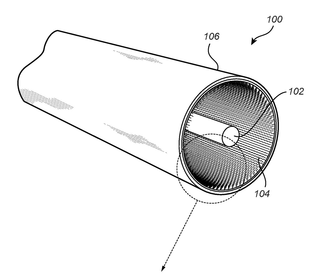
[0038]Referring now to the drawings and to FIGS. 3a and 3b in particular, there is depicted an x-ray source 100. The x-ray source 100 comprises an anode 102, a field emission cathode 104, and an evacuated chamber 106. The evacuated chamber 106 is preferably manufactured from a glass material, having a thickness and chemical construction allowing the evacuated chamber to be transparent to x-ray radiation.

[0039]The anode 102 as well as the field emission cathode ...


PUM

PropertyMeasurementUnit
voltageaaaaaaaaaa
currentaaaaaaaaaa
pressureaaaaaaaaaa

Abstract

The present invention generally relates to an x-ray source and specifically to an x-ray source suitable for large area x-ray generation. The invention also relates to a system comprising such an x-ray source.

Description

TECHNICAL FIELD[0001]The present invention generally relates to an x-ray source and specifically to an x-ray source suitable for large area x-ray generation. The invention also relates to a system comprising such an x-ray source.BACKGROUND OF THE INVENTION[0002]Systems for generation of x-ray radiation are used, for example, in medical diagnostics in order to acquire radiographic images or to produce planar images for technical diagnostic applications. One further effective use of x-ray radiation is in the treatment of substances to reduce the impact of biological and other contamination. For example, food can be irradiated to prolong useful life, making the food safer to consume. Waste water or runoff may be irradiated in the same manner to reduce the effects of contamination.[0003]In the field of technical diagnostic imaging, x-rays are especially effective at penetrating internal structures of a solid object to be examined, and the images formed by the x-rays that pass there thro...

Claims


Application Information

Patent Timeline
Patent Type & Authority Applications(United States)
IPC IPC(8): H01J35/06H01J35/08H05G1/32A61L9/16B03C3/38B03C3/47B03C3/155C02F1/30H01J35/16B03C3/09
CPCH01J35/065A61L2209/11H01J35/08H05G1/32B03C3/09B03C3/383B03C3/47B03C3/155C02F1/307A61L9/16C02F2103/008C02F2209/005C02F2209/003C02F2209/36C02F2303/04H01J35/16B01D53/32B01D2257/91B01D2258/06B01D2259/81B03C3/08B03C3/12C02F1/001H01J2235/068H01J35/112
Inventor TIREN, JONAS
Owner PUREFIZE TECH AB
Why Eureka
Try Eureka