Motor control device and motor control method

a technology of motor control and control device, which is applied in the direction of control system, electrical apparatus, electronic commutators, etc., can solve the problems of increasing the size increasing the circuit scale and cost of the inverter circuit, and increasing the capacitor

Active Publication Date: 2017-08-17
MITSUBISHI ELECTRIC CORP
View PDF1 Cites 16 Cited by
  • Summary
  • Abstract
  • Description
  • Claims
  • Application Information

AI Technical Summary

Benefits of technology

[0022]As a result, it is possible to obtain a small, low-cost motor control device with which an increase in an inter-terminal voltage of a capacitor and an increase in phase currents passe...

Problems solved by technology

As a result, the size of the capacitor increases, making it difficult to achieve reductions in the size and cost of the inverter circuit.
In particular, when the amount of regenerative power that must be consumed by...

Method used


Image

  • Motor control device and motor control method
  • Motor control device and motor control method
  • Motor control device and motor control method

Examples


first embodiment

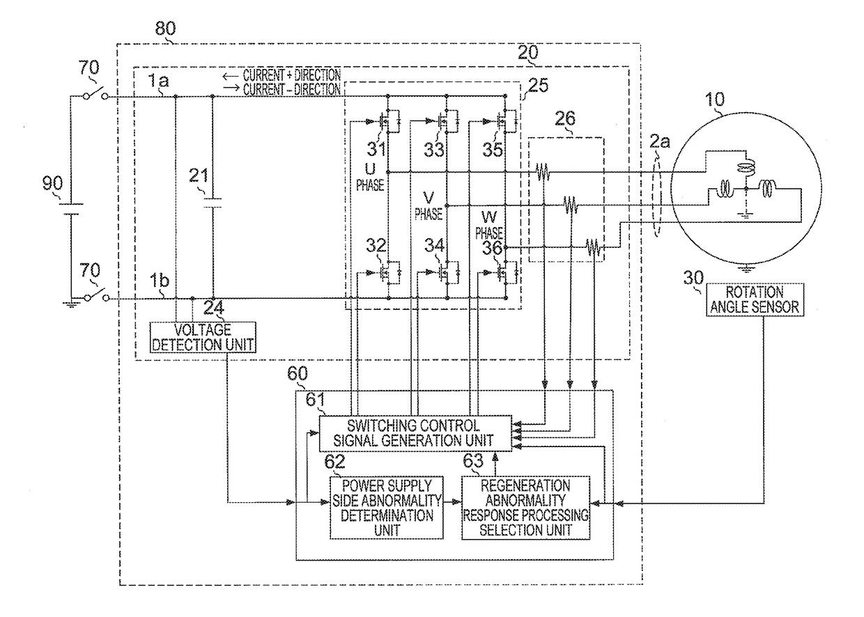
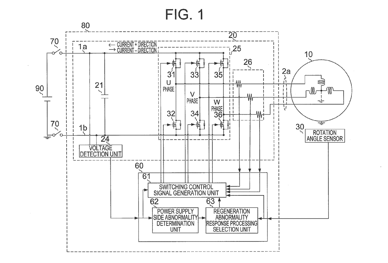
[0029]A motor control device according to a first embodiment of this invention will be described in detail below on the basis of FIGS. 1 and 2. FIG. 1 is a block diagram showing a configuration of a driving system installed with the motor control device according to the first embodiment of this invention. FIG. 1 also shows a DC power supply such as a battery, which supplies DC power to an inverter circuit and is charged with regenerative power, and a three-phase synchronous motor serving as a control subject.

[0030]In FIG. 1, a motor control device 80 is connected to a DC power supply 90 by DC buses 1a, 1b via a power switch 70 so as to exchange driving power and regenerative power with the DC power supply 90. Further, the motor control device 80 is connected to a motor 10 by an AC bus 2a so as to exchange driving power and regenerative power with the motor 10.

[0031]Furthermore, a rotation angle sensor 30 is provided on the motor 10 to detect a rotation angle of the motor. Note that ...

second embodiment

[0093]Next, a motor control device according to a second embodiment of this invention will be described in detail on the basis of FIG. 3. FIG. 3 is a block diagram showing a configuration of a driving system installed with the motor control device according to the second embodiment of this invention. FIG. 3 also shows a DC power supply such as a battery that supplies DC power to an inverter circuit and is charged with regenerative power, and a three-phase synchronous motor serving as a control subject.

[0094]In FIG. 3, the motor control device 80 is constituted by the inverter circuit 20 and the switching control unit 60, similarly to the first embodiment, but differs from the first embodiment in that a DC bus current detection unit 27 is added to the inverter circuit 20 and a regenerative mode determination unit 64 is added to the switching control unit 60.

[0095]Further, the signals input into the power supply side abnormality determination unit 62 and the regeneration abnormality r...


PUM


Abstract

A switching control unit that ON/OFF-controls switching elements of a power conversion circuit includes a power supply side abnormality determination unit, and a regeneration abnormality response processing selection unit that selects either three-phase short circuit processing, in which all upper stage side switching elements or all lower stage side switching elements are switched ON, or six-switch opening processing, in which all of the switching elements of the power conversion circuit are switched OFF, as processing to be executed when the power supply side abnormality determination unit determines that a power supply side abnormality has occurred, the three-phase short circuit processing and the six-switch opening processing being selected in accordance with a motor operating condition of the AC motor at the time of the determination.

Description

BACKGROUND OF THE INVENTION[0001]1. Field of the Invention[0002]This invention relates to a motor control device and a motor control method for drive-controlling an AC motor.[0003]2. Description of the Related Art[0004]An electric vehicle having an AC motor as a driving force source is available in the prior art. In this electric vehicle, traveling drive torque is generated during travel by having the AC motor perform a power running operation, and regenerative braking torque is generated during braking by having the AC motor perform a regenerative operation.[0005]Here, a driving system of the electric vehicle is constituted by a DC power supply, which is constituted by a secondary battery such as a lithium ion battery, an inverter circuit that is connected to the DC power supply and includes a capacitor and a plurality of semiconductor switches, and the AC motor, which is connected to the inverter circuit as a load.[0006]The inverter circuit converts DC power from the DC power supp...

Claims


Application Information

Patent Timeline
IPC IPC(8): H02P29/024H02P6/17H02P27/06
CPCH02P29/024H02P6/17H02P27/06H02P29/027H02P29/0241
Inventor SHINOHARA, RYO
Owner MITSUBISHI ELECTRIC CORP
Why Eureka
Try Eureka