
Infusion flow regulator

a flow regulator and flow rate technology, applied in the direction of packaging foodstuffs, instruments, packaged goods, etc., can solve the problems of inaccurate flow rate regulation and complex structure of the assembly, and achieve the effect of ensuring the flow rate regulation ensuring the accuracy of the assembly, and easy manufacturing

Active Publication Date: 2017-08-24
HANVIT MD
View PDF3 Cites 1 Cited by
  • Summary
  • Abstract
  • Description
  • Claims
  • Application Information

AI Technical Summary

Benefits of technology

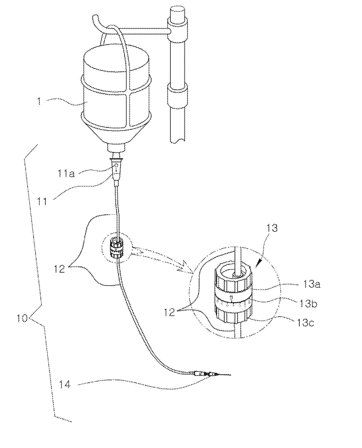
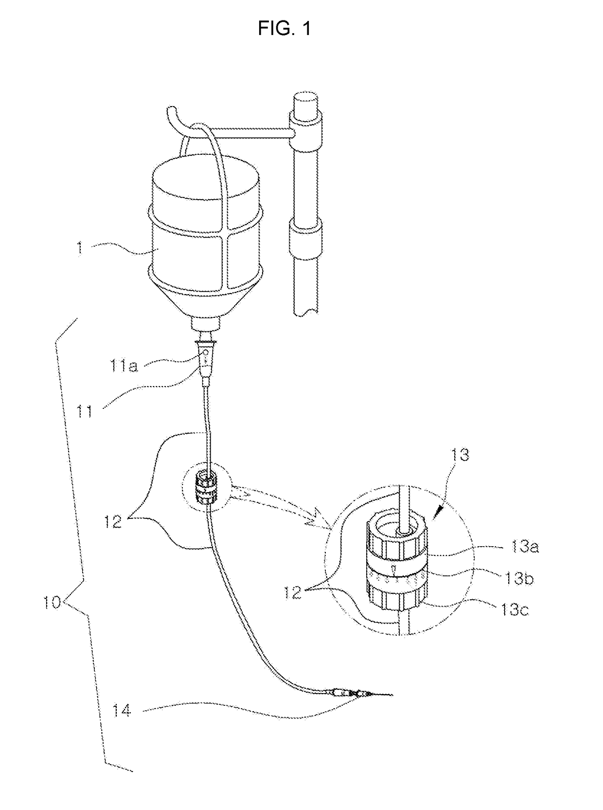
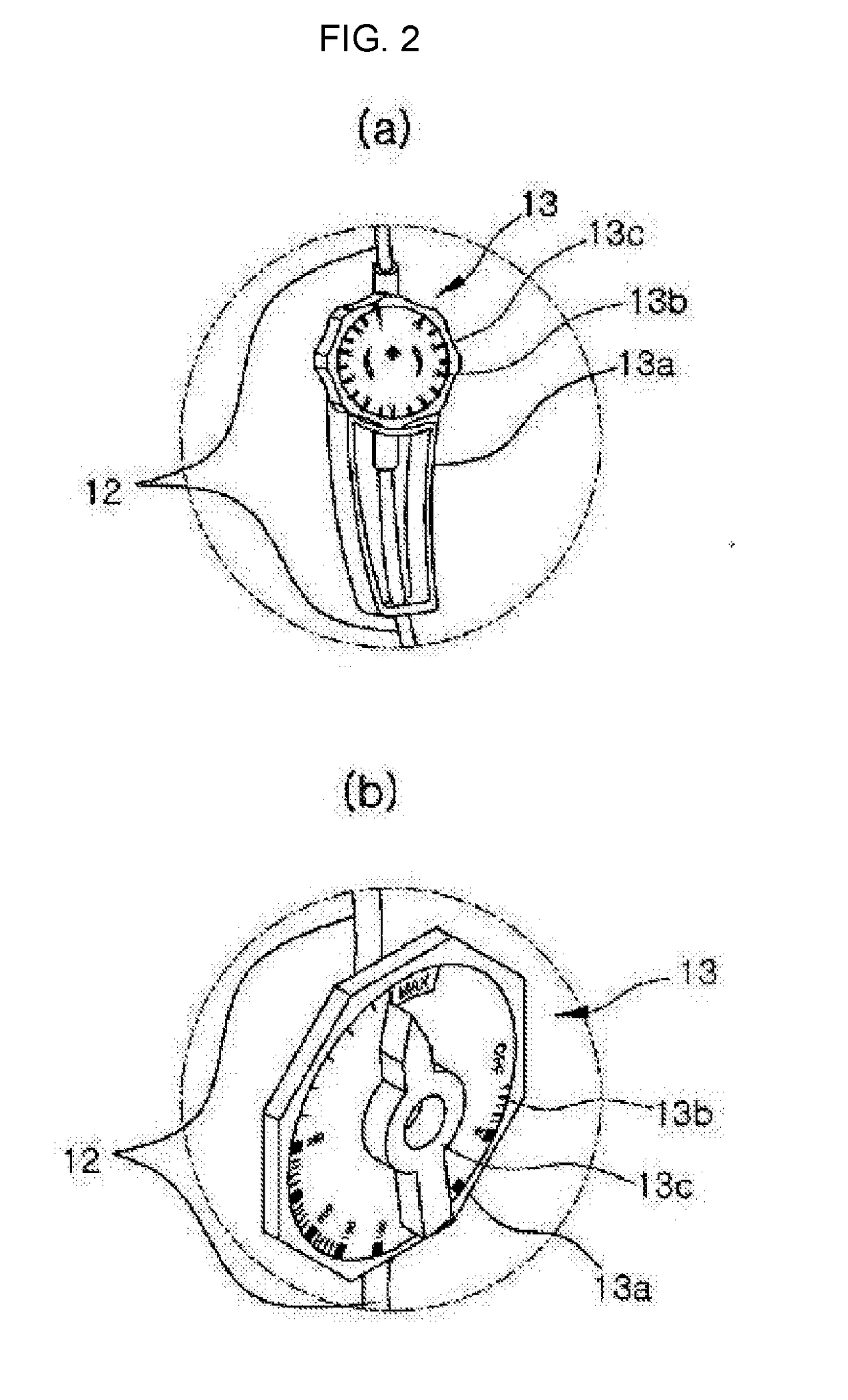
The present invention is a device for regulating the flow rate of an infusion solution. It has several technical effects. Firstly, it is easy to manufacture because it has both an arc-shaped flow path and a circular flow path on a single flat surface, and a sealing member is formed as a single plate, ensuring precise processing without any errors. Secondly, it solves the problem of movement of the tube when flow rate is regulated, as the first body is mounted at one surface of a second body and a handle is connected to the tube, stabilizing it. Thirdly, the arrangement positions of gradations and protrusions on the first body are designed to improve readability and facilitate flow rate regulation. Fourthly, the cross-sectional area of the connecting flow path is larger than that of the circular flow path, allowing the infusion solution to flow smoothly and remove bubbles effectively. Fifthly, the arc-shaped flow path is designed to provide a precise flow rate regulating ability and stability in use, with a maximum flow rate being appropriately limited and a section in which flow rate will be precisely regulated being secured.

Problems solved by technology

However, in Korean Patent Publication No. 10-2003-0044181 and Korean Patent Registration No. 10-0468222, because the arc-shaped flow path and the discharge guide groove are formed at different installation surfaces, the arc-shaped flow path and the discharge guide groove are each sealed with separate rubber packing, and a structure thereof is complex.
Therefore, although the arc-shaped flow path and the discharge guide groove should be able to accurately regulate a flow rate by rotation of the first body by the two installation surfaces, the rubber packing installation structure, and the coupling structure between the body and the first body being precise manufactured and then assembled, precisely manufacturing is difficult due to the complexity of the structure, and a flow rate may be inaccurately regulated due to a manufacturing error in an actually assembled state.

Method used


Image

  • Infusion flow regulator
  • Infusion flow regulator
  • Infusion flow regulator

Examples


Embodiment Construction

[0036]Hereinafter, exemplary embodiments of the present invention will be described with reference to the accompanying drawings in order to enable those of ordinary skill in the art to easily embody and practice the invention.

[0037]FIGS. 3A-3B and 4A-4E are views for describing an exterior of an infusion flow regulator according to an embodiment of the present invention. FIGS. 3A-3B are a front perspective view (a) and an unfolded view (b) of gradations 270 engraved along a circumferential direction of a first body 200, and FIGS. 4A-4E are a top view (a), a left view (b), a front view (c), a right view (d) and a rear view (e).

[0038]FIGS. 5 to 10 are views for describing elements of the infusion flow regulator according to the embodiment of the present invention. FIG. 5 is a view illustrating an exploded infusion flow regulator in a front perspective view, FIG. 6 is a view illustrating the exploded infusion flow regulator in a rear perspective view, FIG. 7 is a rear perspective view ...


PUM


Abstract

The present invention relates to an infusion flow adjuster which is used in order to adjust the flow rate of an infusion solution to be administered when performing infusion therapy, and relates to an infusion flow adjuster in which an arc-shaped flow path for adjusting the distance through which the infusion solution passes and a circular flow path for inducing discharge of the infusion solution that has passed through the arc-shaped flow path are constituted in a single plane, and which is easy to produce as a product for accurately adjusting the flow rate, affords convenience of handling being provided with a handle in a suitable position, and also, in addition to allowing fine adjustment of the flow rate, limits the maximum flow rate to an appropriate value, so being convenient to use during actual infusion therapy.

Description

CROSS REFERENCE PARAGRAPH[0001]This application is a U.S. National Stage of PCT / KR2015 / 010054, filed Sep. 24, 2015, which claims the priority benefit of Korean Patent Application No. 10-2014-0141917, filed on Oct. 20, 2014 in the Korean Intellectual Property Office, the disclosures of which are incorporated herein by reference.TECHNICAL FIELD[0002]The present invention relates to an infusion flow regulator used in regulating a flow rate of an infusion solution to be administered when an infusion solution treatment is performed, and more particularly, to an infusion flow regulator that can be easily manufactured as a product capable of precisely regulating a flow rate because an arc-shaped flow path configured to regulate a distance through which an infusion solution passes and a circular flow path configured to guide discharge of the infusion solution that has passed through the arc-shaped flow path are formed on a single plane, can be easily handled because of a handle formed at an...

Claims


Application Information

Patent Timeline
Patent Type & Authority Applications(United States)
IPC IPC(8): A61M5/168A61M5/36
CPCA61M5/16804A61M5/36A61M2207/00A61M2205/583A61M2205/3379A61J1/20A61M5/16813A61M2205/3334A61M5/1417A61M5/16881A61M5/168
Inventor LEE
Owner HANVIT MD
Learn More