
Reinforced wind tower

a technology of wind turbines and reinforced beams, which is applied in the direction of machines/engines, renewable energy generation, greenhouse gas reduction, etc., can solve the problems of increasing costs, dimensional limitations imposed by road transportation on the tower segments, and the diameter of the bottom segments generally exceeding the allowed limits

Inactive Publication Date: 2017-08-24
GAMESA INNOVATION & TECH SA
View PDF12 Cites 0 Cited by
  • Summary
  • Abstract
  • Description
  • Claims
  • Application Information

AI Technical Summary

Benefits of technology

This patent describes a wind turbine tower with inner reinforcements that allow for larger towers to be designed with smaller diameters, reducing costs and assembly times. The inner structure also helps select the natural frequency of the tower to improve fatigue resistance and reduce tension loads. Additionally, the inner structure can be designed to not interfere with internal elements of the tower. Overall, the reinforced wind turbine tower provides a simple and effective solution to current tower designs.

Problems solved by technology

Both embodiments have drawbacks that generate construction problems of these towers and greatly increase the cost thereof.
One of these drawbacks is the dimensional limitations imposed by road transport the tower segments, given that although if the tower is divided into segments to facilitate transportation, the diameter of the bottom segments generally exceeds the allowed limits.
An additional drawback is that to withstand the high loads to which the tower is subjected, the hoops or plates forming the segments must have a considerable thickness, which implies high costs for materials.
In addition, depending on the tower height and loads that they must withstand, some towers cannot be designed due to the aforementioned transport constraints.
Thus, the higher loads require a greater height of these segments is required, although as the height of this segment increases also increases the total cost of the tower.
However, although with this solution the drawback of road transport restrictions is solved, the laborious assembly of the tower, part by part, as well as the increased assembly time required, result in an important production cost.
In addition, this solution does not add stiffness to the tower, so that at greater heights and loads a high plate thickness is still required, which significantly increases the tower final price.

Method used


Image

  • Reinforced wind tower
  • Reinforced wind tower
  • Reinforced wind tower

Examples


Embodiment Construction

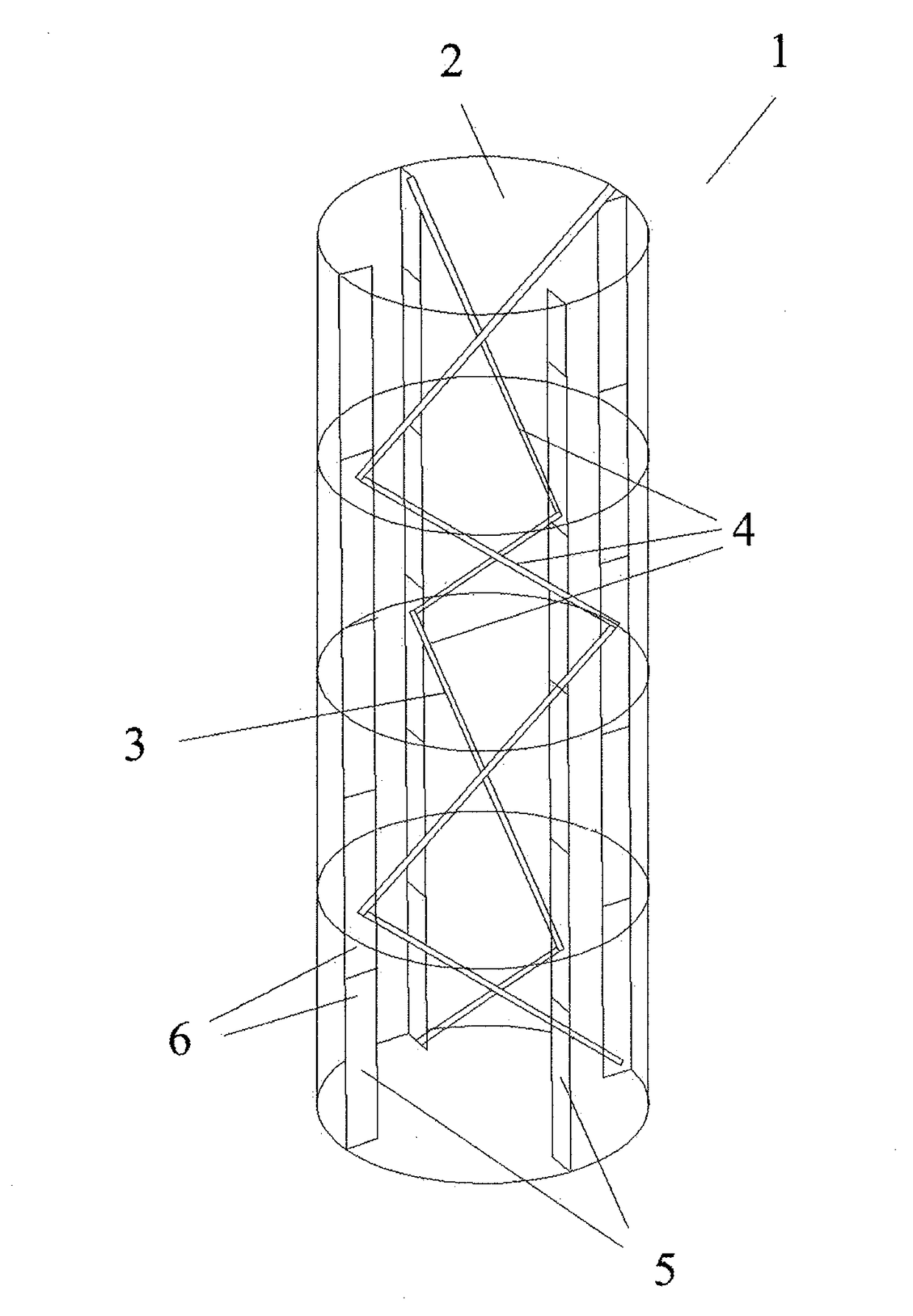
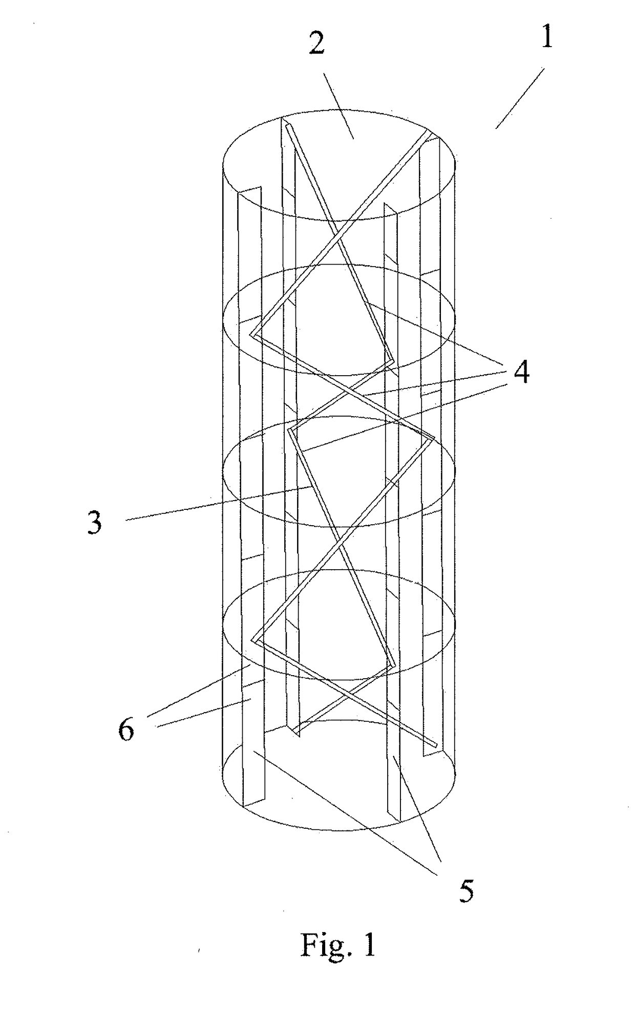
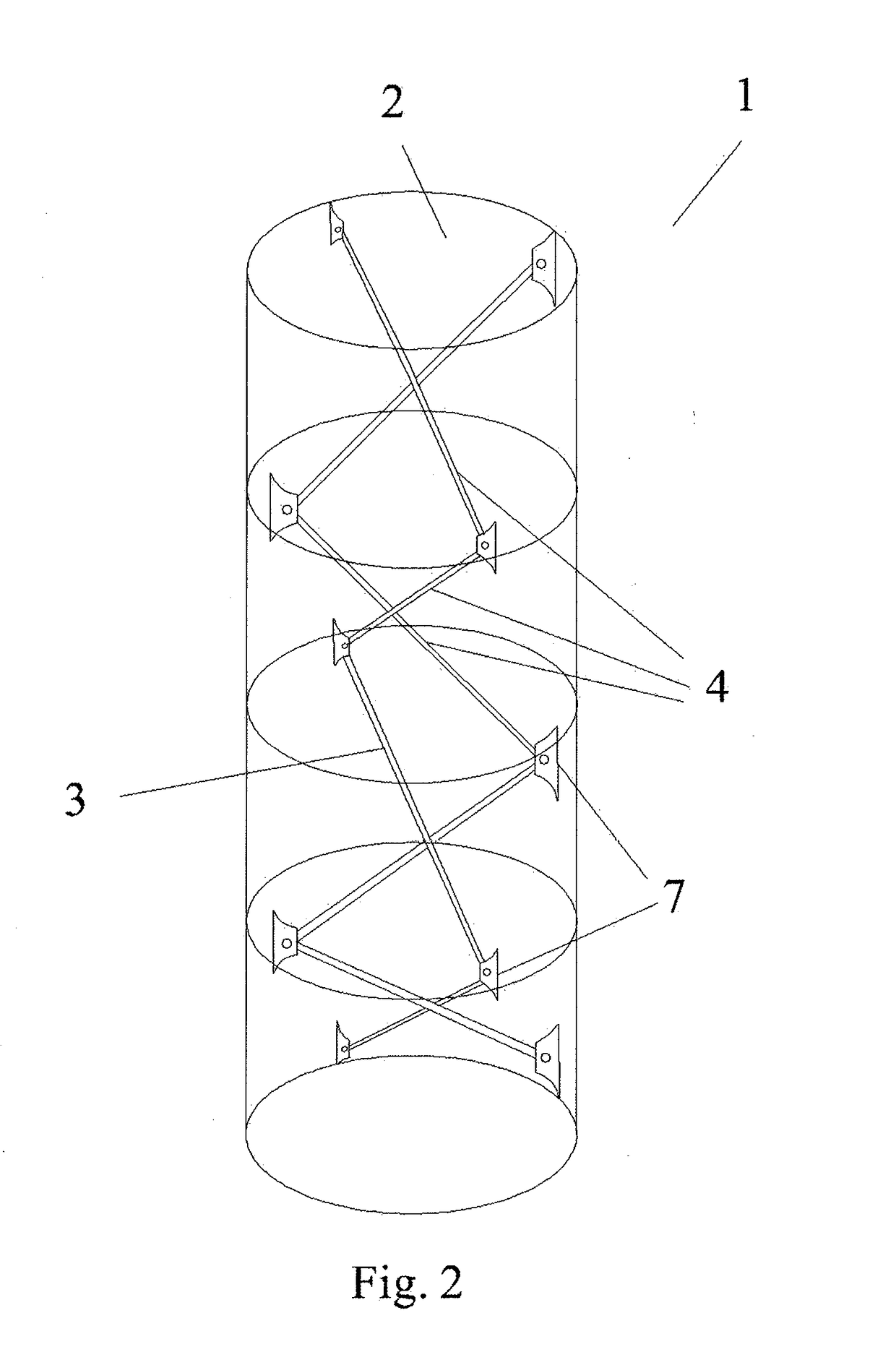
[0016]The reinforced wind turbine tower formed by a hollow body disclosed herein comprises in its interior at least one reinforcement structure formed by a series of longitudinal reinforcement elements, where each of said longitudinal reinforcement elements has its two opposite ends attached by attachment means to the inner surface of the tower hollow body at points in different vertical lines, and where each longitudinal element has at least one of its ends attached by attachment means to the end of other longitudinal element consecutive to it.

[0017]According to a preferred embodiment, the wind turbine tower comprises in its interior at least two vertical reinforcement structures, each one formed by a series of reinforcements with a longitudinal shape and attached to each other consecutively at their ends, where each vertical reinforcement structure is attached to the hollow body inner surface.

[0018]In this case, in a preferred embodiment, the vertical reinforcement structures have...


PUM


Abstract

Reinforced wind turbine tower (1) formed by a hollow body (2), which comprises in its interior at least one reinforcement structure (3) formed by a series of longitudinal reinforcements (4), where each of said reinforcements (4) has its two opposite ends attached by attachment means to the hollow body inner surface (2) of the tower at points placed on different vertical lines, and where each reinforcement (4) has at least one of its ends attached by attachment means to the end of the other consecutive reinforcement (4) with the same.

Description

TECHNICAL FIELD OF THE INVENTION[0001]The present invention belongs to the technical field of wind turbine towers, which are formed by a very high hollow body subjected to a number of loads.BACKGROUND OF THE INVENTION[0002]Currently with the increased generation of clean, environmentally-friendly power, wind power has been growing development, generating an increased number of wind turbines to obtain wind power which generally comprises a turbine, a high tower and a generator.[0003]The tower can be made of reinforced concrete or metal, and the construction and problematic thereof is similar to other high towers, such as broadcasting towers, mobile communications towers or electricity towers, although the specification focuses on wind turbine towers it is not limited to these.[0004]Metal towers are formed by superposing metal rings or hoops welded to each other such that they form segments of the tower, or by joining together, usually by crewing together, metal panels that are joined...

Claims


Application Information

Patent Timeline
Patent Type & Authority Applications(United States)
IPC IPC(8): E04H12/08F03D13/20
CPCE04H12/08E04H12/342F03D13/20F05B2240/912Y02E10/74Y02E10/728F03D3/062E04H12/20Y02E10/72E04H12/02
Inventor UNANUA HERMOSO DE MENDOZA, PABLO
Owner GAMESA INNOVATION & TECH SA
Learn More