X-ray imaging device

Active Publication Date: 2017-08-31
VA TECHNOLOGIE +1
View PDF0 Cites 2 Cited by
  • Summary
  • Abstract
  • Description
  • Claims
  • Application Information

AI Technical Summary

Benefits of technology

The present invention provides a tomographic image of a layer between a rotating axis and an X-ray source. This allows for TMJ PA mode imaging, which is conventionally possible in a three-axis drive system, with a mechanical configuration similar to a dental X-ray panoramic imaging device using a conventional two-axis drive system. This invention is advantageous for miniaturization and easy to operate.

Problems solved by technology

However, the conventional dental X-ray panoramic imaging device has some limitations.
One of the limitations is that even when the image layer between the rotating axis and the X-ray sensor is radiographed, a portion between the rotating axis and the X-ray source affects a panoramic image.
Another one is that due to a physical limitation of a device configuration, an image layer, which is allowed to be radiographed as an X-ray panoramic image, is limited to layers between the X-ray sensor and the rotating axis of the rotating arm.
FIG. 2 shows a problem occurring when attempting TMJ PA mode imaging by using conventional dental X-ray panoramic imaging device.
For the above reasons, TMJ PA mode imaging is not realized in the conventional X-ray panoramic imaging device having a two-axis drive system, but is provided only in a device having a three-axis drive system, that is, a mechanically larger, more complex and more expensive device capable of moving a location of the rotating axis two-dimensionally.

Method used


Image

  • X-ray imaging device
  • X-ray imaging device
  • X-ray imaging device

Examples


Embodiment Construction

[0041]Reference will now be made in greater detail to exemplary embodiments of the present invention, an example of which is illustrated in the accompanying drawings. Although preferred embodiments of the present invention have been described for a dental X-ray panoramic imaging device, those skilled in the art will appreciate that the present invention can be applied to a two-dimensional tomographic imaging device, without departing from the scope and spirit of the invention as disclosed in the accompanying claims.

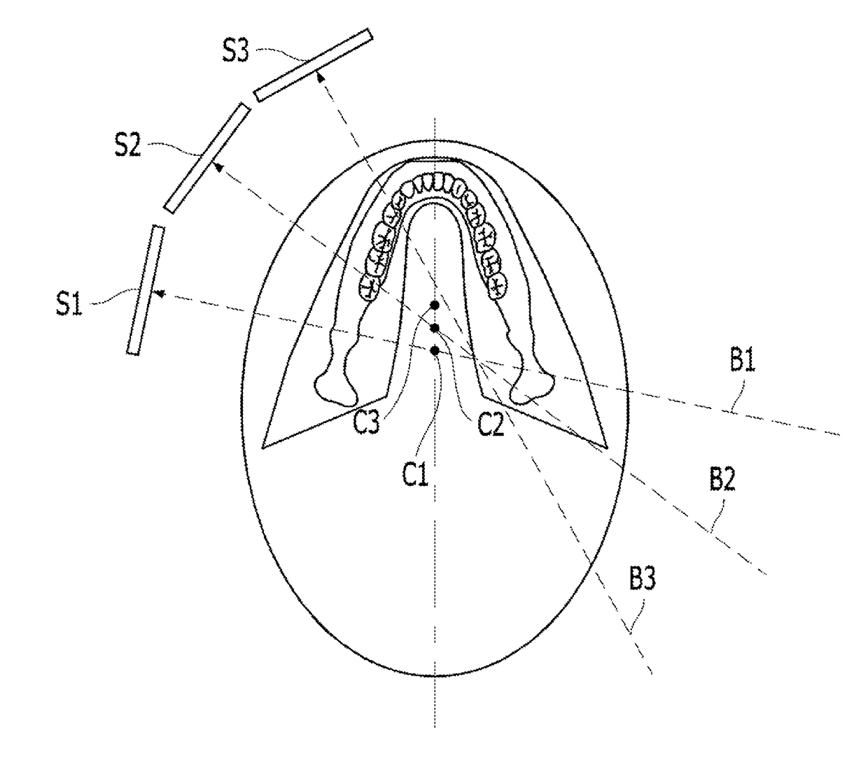
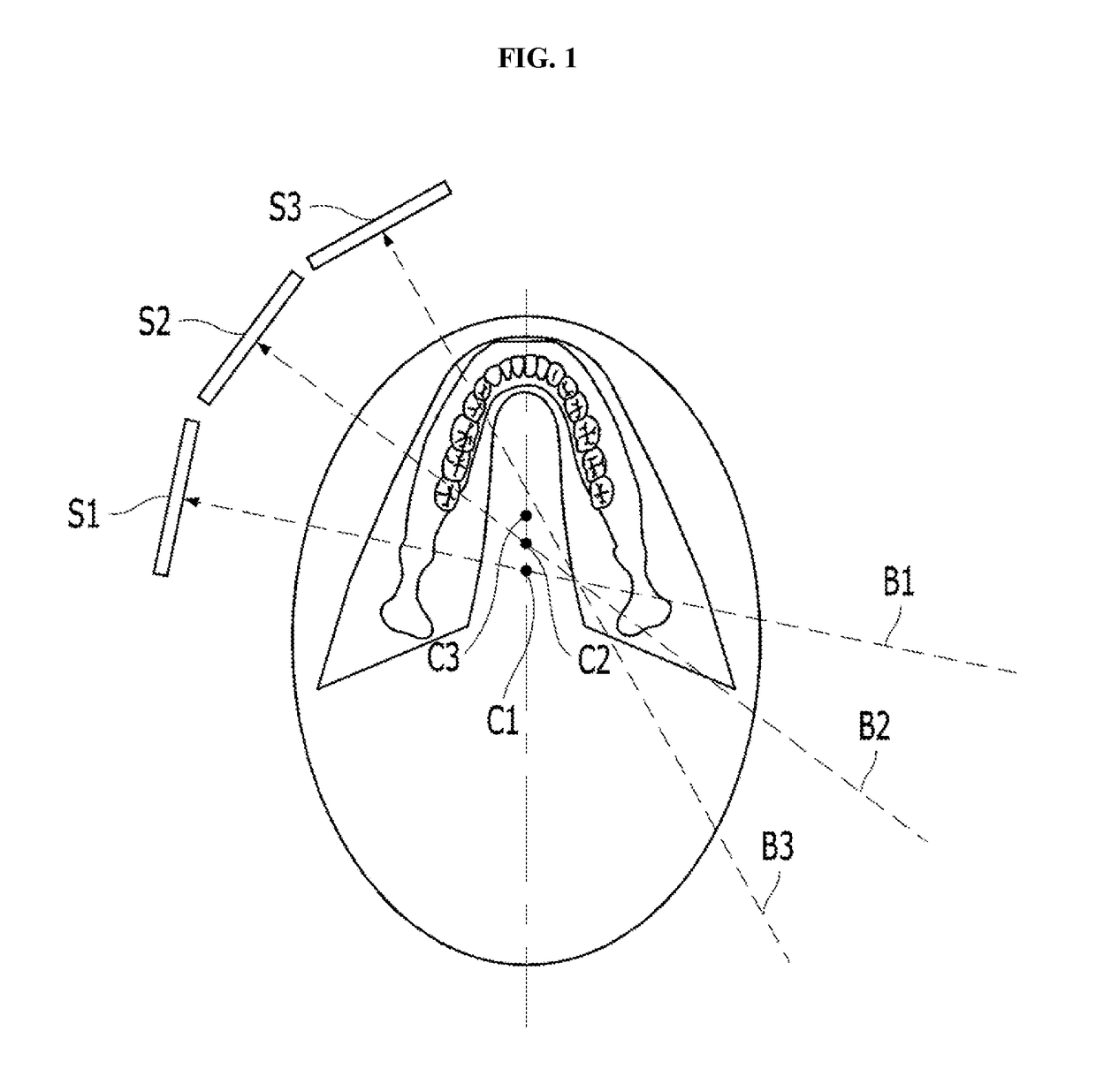
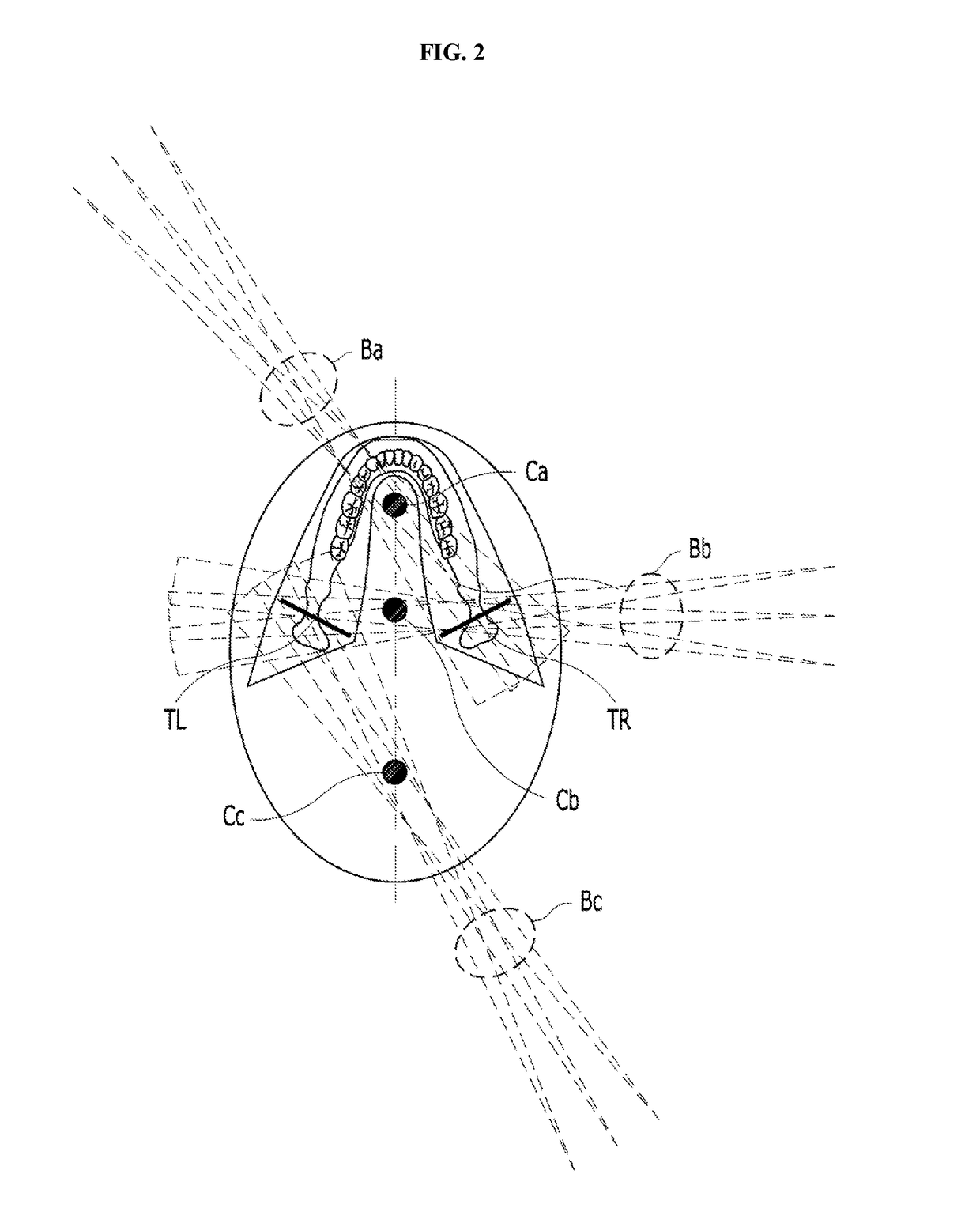
[0042]FIG. 3 shows radiographing in multiple directions in a two-dimensional tomographic imaging device according to an embodiment of the present invention.

[0043]The two-dimensional tomographic imaging device according to the embodiment of the present invention includes: a radiography unit having an X-ray source and an X-ray sensor disposed to face each other with a rotating axis therebetween; and a driver configured to rotate the X-ray source and the X-ray sensor about t...


PUM


Abstract

Disclosed is an X-ray imaging device, which is capable of providing a tomographic image of an image layer disposed between an axis of rotation and an X-ray source. The imaging device according to the present invention includes a radiography unit having an X-ray source and an X-ray sensor disposed to face each other with a rotating axis therebetween, wherein the X-ray sensor configured to obtain X-ray transmission images, a driver configured to rotate the X-ray source and the X-ray sensor about the rotating axis, and an image processor configured to provide a two-dimensional tomographic image of an image layer disposed between the rotating axis and the X-ray source, by shifting and overlapping the X-ray transmission images after reversing left and right at least some of the X-ray transmission images.

Description

TECHNICAL FIELD[0001]The present invention generally relates to a two-dimensional tomographic imaging device and a method for same. More particularly, the present invention relates to an imaging device and a method for same, in which an X-ray imaging device includes an X-ray source and an X-ray sensor facing each other with an object therebetween, and a driver driving the X-ray source and the X-ray sensor about a rotating axis therebetween, whereby the X-ray imaging device is capable of providing a two-dimensional tomographic image of an image layer disposed between the rotating axis of the driver and the X-ray source.BACKGROUND ART[0002]X-rays are attenuated according to an X-ray attenuation coefficient, such as photoelectric effect, Compton scattering, and the like, of a substance placed in a path of the X-rays.[0003]X-ray imaging modality is radiography using permeability of X-rays, in which an X-ray image of an inner structure of an object is obtained based on an amount of atten...

Claims


Application Information

Patent Timeline
IPC IPC(8): A61B6/14A61B6/00G01N23/04A61B6/03
CPCA61B6/14G01N23/046A61B6/4452A61B6/03A61B6/025A61B6/4435A61B6/5205G06T3/00G06T11/005G06T2207/10072G06T2207/10116G06T2207/30036A61B6/51
Inventor CHOI, SUNGIL
Owner VA TECHNOLOGIE
Why Eureka
Try Eureka