
Calibration device

a calibration device and blood-reagent technology, which is applied in the field of calibration devices, can solve the problems of unstable reaction of blood with reagents, limited shelf life of calibration samples, and high cost and time consumption of calibration procedures, so as to reduce degradation, simple and cheap construction, and the effect of greater realism

Inactive Publication Date: 2017-08-31
CSEM CENT SUISSE DELECTRONIQUE & DE MICROTECHNIQUE SA RECH & DEV +1
View PDF9 Cites 1 Cited by
  • Summary
  • Abstract
  • Description
  • Claims
  • Application Information

AI Technical Summary

Benefits of technology

The patent describes a calibration device that can replace actual biological samples used for calibration. The device is made from printed material that can have a long shelflife, eliminating the need for repeated preparation of samples. The device can also be duplicated for use as a standard for all diagnostic devices of a particular model. Compared to using genuine biological samples for calibration, the device can simulate real reactions, 3D effects, and cameral limitations. Overall, the technical effects include improved repeatability and efficiency in calibration.

Problems solved by technology

Since real biological samples are used for calibration, the reaction of the blood with the reagent is unstable over time.
In consequence, the shelf life of the calibration samples is limited to several hours, requiring new calibration samples to be produced every time the diagnostic laboratory equipment must be calibrated, which furthermore requires a stock of appropriate biological material to be maintained.
In consequence, such calibration procedures are expensive and time-consuming.
Although these methods can calibrate the camera parameters, such as focus, colour response, etc. of the diagnostic device, they cannot simulate real reactions, 3D effects and camera limitations (such as fisheye, undesirable borders etc.) and thus cannot be used for calibrating the diagnostics performed by the diagnostic device.

Method used


Image

  • Calibration device
  • Calibration device
  • Calibration device

Examples


Embodiment Construction

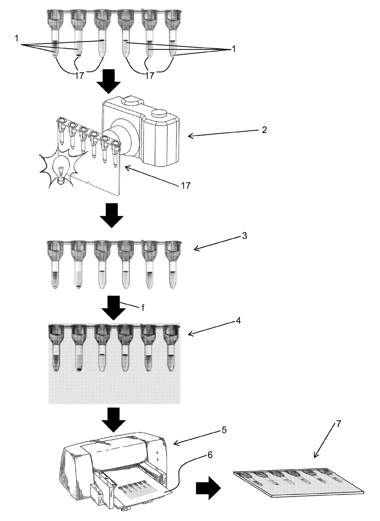
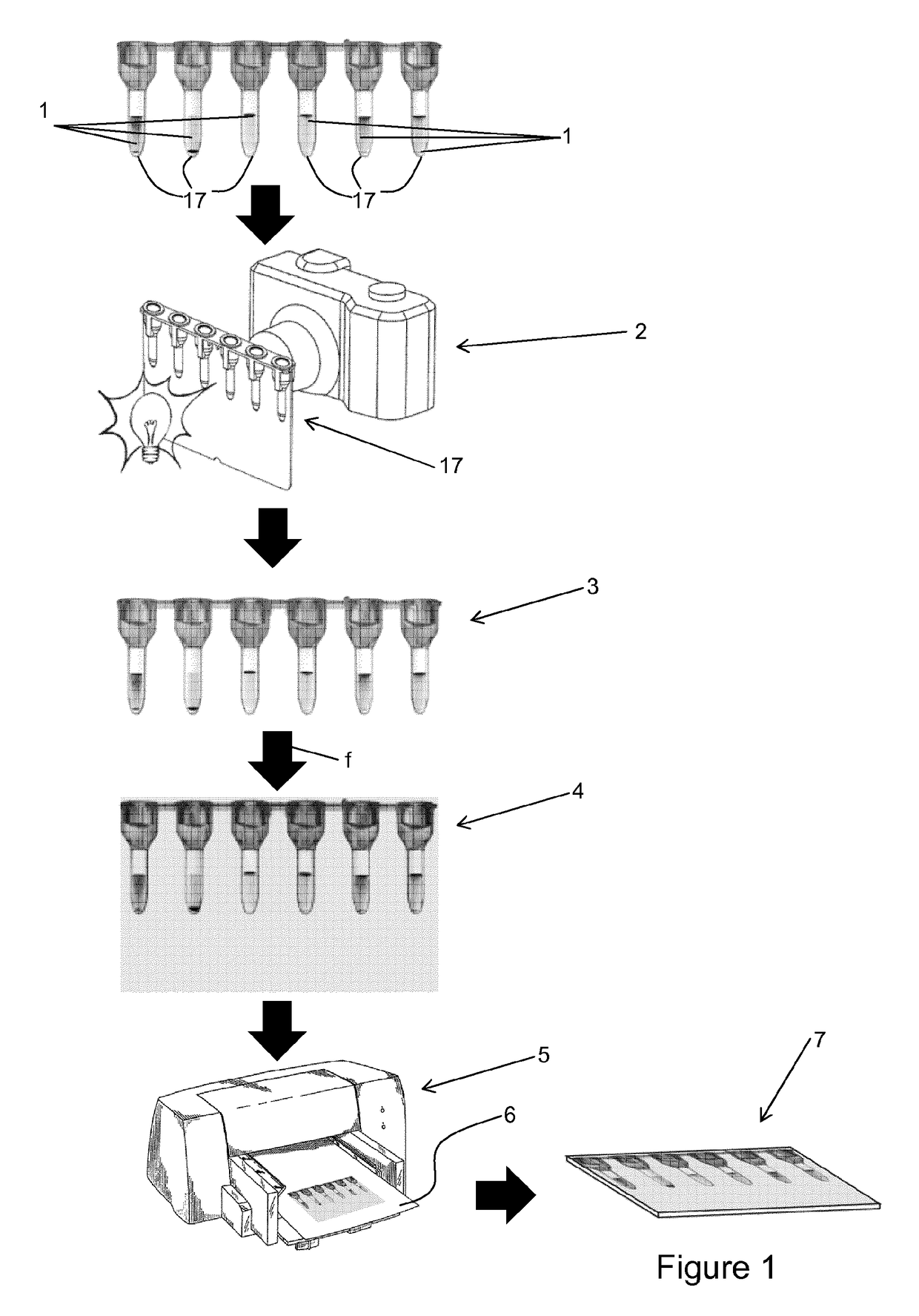
[0032]FIG. 1 illustrates schematically a method of manufacturing a calibration device according to the invention.

[0033]Firstly, at least one biological sample 1 of known properties is introduced into at least one sample container 17, as is conventionally known. In this case, a bio-card of six sample containers 17 is illustrated. This biological sample 1 may e.g. comprise one or more blood samples of known blood group, treated with appropriate reagents. These reagents may cause coagulation, colour changes, and / or floating or settling out to varying degrees of the solid reaction products. These changes are typically determinant for diagnosing the known properties of the biological samples.

[0034]Subsequently, the sample containers 17 containing the biological samples 1 are digitally imaged, either by utilising a digital imaging device 2 such as a digital camera of a diagnostic device of the type for which the calibration device is intended, or by a separate digital camera. This imaging...


PUM

PropertyMeasurementUnit
diameteraaaaaaaaaa
diameteraaaaaaaaaa
thicknessaaaaaaaaaa

Abstract

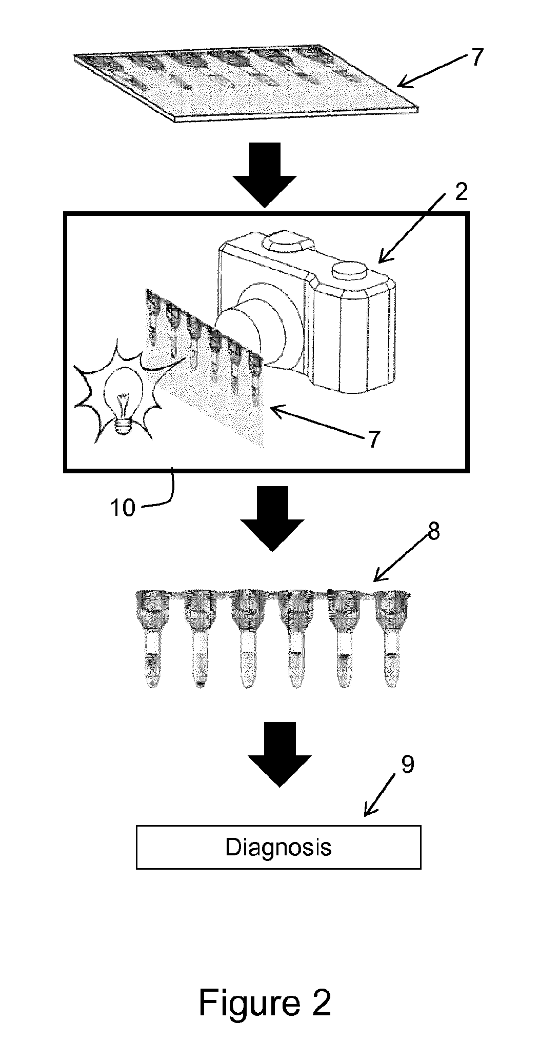
Calibration device for a diagnostic device, the diagnostic device comprising a digital imaging device arranged to record an image of at least one sample container containing at least one biological sample. According to the invention, methods include of digitally imaging said at least one sample container, thus obtaining a first image processing the first image, thus obtaining a second image printing a representation of the second image onto a substrate by means of a printing method, thus obtaining the calibration device, wherein said processing of the first image comprises applying at least one transfer function to the first image. The invention further relates to a corresponding calibration device, and a method of calibrating a diagnostic device by means of the calibration device.

Description

TECHNICAL FIELD[0001]The present invention relates to the field of diagnostic laboratory equipment. More particularly, it relates to calibration devices for the calibration of such diagnostic devices.STATE OF THE ART[0002]Diagnostic laboratory equipment for automated diagnosis must be calibrated periodically to ensure their accuracy. Recent EU regulation requires that such diagnostic devices be calibrated using a standardised and reproducible procedure. As an example, in the case of blood analysis, the diagnostic device is typically calibrated using real blood samples with known properties (e.g. blood type, presence of pathogens), to determine whether the diagnostic device correctly diagnoses these known properties. If not, the diagnostic device is adjusted appropriately, or sent for repair. Typically, a blood sample of known properties is introduced into a container which contains a reagent, with which the blood sample reacts to a greater or lesser extent, generating a pattern char...

Claims


Application Information

Patent Timeline
Patent Type & Authority Applications(United States)
IPC IPC(8): G01N21/27A61B5/00H04N1/60H04N17/00G06T7/80
CPCG01N21/278H04N17/002A61B2560/0223H04N1/6033A61B5/0059G06T7/80G01N35/00623G01N2001/2893G01N2035/0412
Inventor MEIER, GERMANOPUGIN, RAPHAELHASLER, DAVIDSCOLAN, EMMANUEL
Owner CSEM CENT SUISSE DELECTRONIQUE & DE MICROTECHNIQUE SA RECH & DEV
Learn More