Foreign object detection device

a foreign object and detection device technology, applied in the direction of instruments, inductances, reradiation, etc., can solve the problems of generating heat, eddy current to foreign objects, heat generation may be caused by hysteresis loss, etc., and achieve the effect of high sensitivity of foreign object detection

Active Publication Date: 2017-08-31
PANASONIC INTELLECTUAL PROPERTY MANAGEMENT CO LTD
View PDF3 Cites 12 Cited by
  • Summary
  • Abstract
  • Description
  • Claims
  • Application Information

AI Technical Summary

Benefits of technology

[0010]With the present invention, a foreign object detection device that has a high sensitivity of foreign object detection can be provided.

Problems solved by technology

The presence of a foreign object which is a conductive material, such as metal, between the power supply device and the power receiving device may cause an eddy current to the foreign object which then may possibly generate heat.
When the foreign object is a ferromagnet, such as iron, heat generation may be caused by hysteresis loss.
In particular, when the wireless charging system transmits high power, a large amount of heat may be generated by the foreign object.

Method used


Image

  • Foreign object detection device
  • Foreign object detection device
  • Foreign object detection device

Examples


embodiment 1

[0039]A foreign object detection device according to Embodiment 1 is described with reference to the drawings.

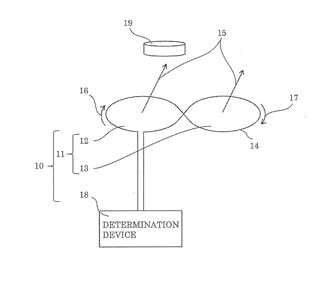
[0040]FIG. 1 is a diagram showing an operating principle of the foreign object detection device according to Embodiment 1. Foreign object detection device 10 includes set sensor coil 11 and determination device 18. Set sensor coil 11 includes a plurality of unit set sensor coils including unit set sensor coil 12 and unit sensor coil 13. Each external shape of unit sensor coil 12 and unit sensor coil 13 is prescribed by coil conductor 14. Coil conductors 14 are continuously connected and electrically connected in series. A set of unit sensor coils having the external shapes prescribed by coil conductors 14 that are continuously connected and electrically connected in series is defined as a sensor coil group. FIG. 1 shows only one sensor coil group, which is thus set sensor coil 11. Each of unit sensor coil 12 and unit sensor coil 13 generates an electromotive force by a chang...

embodiment 2

[0099]FIG. 8 is a diagram showing a basic configuration of main components of a foreign object detection device according to Embodiment 2. Note that FIG. 8 is a perspective view.

[0100]Foreign object detection device 127 includes set sensor coil group 120, switch 125, and determination device 126. Set sensor coil group 120 includes first set sensor coil 121, second set sensor coil 122, third set sensor coil 123, and fourth set sensor coil 124.

[0101]Switch 125 selectively drives first set sensor coil 121, second set sensor 15 coil 122, third set sensor coil 123, and fourth set sensor coil 124. Determination device 126 has the same function as determination device 18 according to Embodiment 1.

[0102]Each of first set sensor coil 121, second set sensor coil 122, third set 20 sensor coil 123, and fourth set sensor coil 124 has the same configuration as sensor coil group 60 shown in FIG. 5A.

[0103]Second set sensor coil 122 is arranged to be offset with respect to first set sensor coil 121 ...

embodiment 3

[0114]FIG. 10 is a conceptual diagram showing a unit sensor coil included in a foreign object detection device according to Embodiment 3.

[0115]Unit sensor coil 150 includes coil conductor 151 and switches 155, 156, and 157. Coil conductor 151 includes reference conductor 152, first adjusting conductor 153, and second adjusting conductor 154. Reference conductor 152 is placed on the outermost periphery of unit sensor coil 150. First adjusting conductor 153 and second adjusting conductor 154 are placed to create shortcuts of reference conductor 152. Switch 155 is placed in reference conductor 152. Switch 156 is placed between reference conductor 152 and first adjusting conductor 153. Switch 157 is placed between reference conductor 152 and second adjusting conductor 154.

[0116]When switch 155 is closed (that is, turned “On”) and switches 156 and 157 are opened (that is, turned “Off”), a closed loop formed as the unit sensor coil by reference conductor 152 induces an electromotive force...


PUM

PropertyMeasurementUnit
electromotive forceaaaaaaaaaa
lengthaaaaaaaaaa
voltageaaaaaaaaaa

Abstract

A foreign object detection device in the present disclosure includes: a set sensor coil; and a determination device that detects a foreign object, based on voltage of the set sensor coil. A first sensor coil group in the set sensor coil includes unit sensor coils wound in a first winding direction and unit sensor coils wound in a second winding direction opposite to the first winding direction, these coils wound in the respective directions being electrically connected in series. Each unit sensor coil includes a coil conductor prescribing its external shape. Coil conductors are continuously and electrically connected in series. A part or the whole of the coil conductor forming the unit sensor coil in the first winding direction is a part or the whole of the coil conductor forming the unit sensor coil in the second winding direction.

Description

TECHNICAL FIELD[0001]The present disclosure relates to wireless charging, with which electric power is transmitted in a non-contact manner, and to a foreign object detection device which detects a foreign object that influences the power transmission.BACKGROUND ART[0002]The technique of supplying power in a non-contact manner is called wireless charging. An example of a wireless charging system includes a power supply device on the power supply side and a power receiving device on the power receiving side, and transmits power through electromagnetic induction or magnetic resonance. Such a wireless charging system has been studied for its application to the transmission of high power used for, for example, charging of an electric vehicle, in addition to the transmission of low power used by, for example, a cellular phone or an electric toothbrush.[0003]The presence of a foreign object which is a conductive material, such as metal, between the power supply device and the power receivi...

Claims


Application Information

Patent Timeline
Patent Type & Authority Applications(United States)
IPC IPC(8): G01V3/10H01F27/28
CPCH01F27/28G01V3/108H01F5/00H01F38/14H02J50/60
Inventor ADACHI, KAZUHIRO
Owner PANASONIC INTELLECTUAL PROPERTY MANAGEMENT CO LTD
Why Eureka
Try Eureka