Incandescent lamp

a technology of incandescent lamps and incandescent lamps, which is applied in the direction of discharge tube main electrodes, transportation and packaging, lighting and heating apparatus, etc., can solve the problems of vibration and impact on the motor, and achieve the effects of improving the adhesion to the bridge, improving the vibration resistance and impact resistance of the incandescent lamp, and improving the degree of coupling

Active Publication Date: 2017-08-31
STANLEY ELECTRIC CO LTD
View PDF1 Cites 0 Cited by
  • Summary
  • Abstract
  • Description
  • Claims
  • Application Information

AI Technical Summary

Benefits of technology

The present invention provides an incandescent lamp with reinforced vibration resistance and impact resistance. This is achieved through a configuration where the first and second zones, with higher Younge's moduli than the Dumet wire or nickel plating film-fitted Dumet wire of the third zone, occupy the standing portion to increase stiffness and reinforce vibration resistance and impact resistance. This prevents holding part disconnection further. The first zone, formed of a non-alloy, single material with a high melting point, suppresses embrittlement of the holding part of the lead wire holding the filament and prevents disconnection. Additionally, the surface area of the part of the second zone penetrating through the bridge increases, improving adhesion to the bridge and overall vibration resistance and impact resistance of the incandescent lamp.

Problems solved by technology

Incandescent lamps loaded in, for example, automobiles are subject to vibration and impact.

Method used


Image

  • Incandescent lamp
  • Incandescent lamp
  • Incandescent lamp

Examples


Embodiment Construction

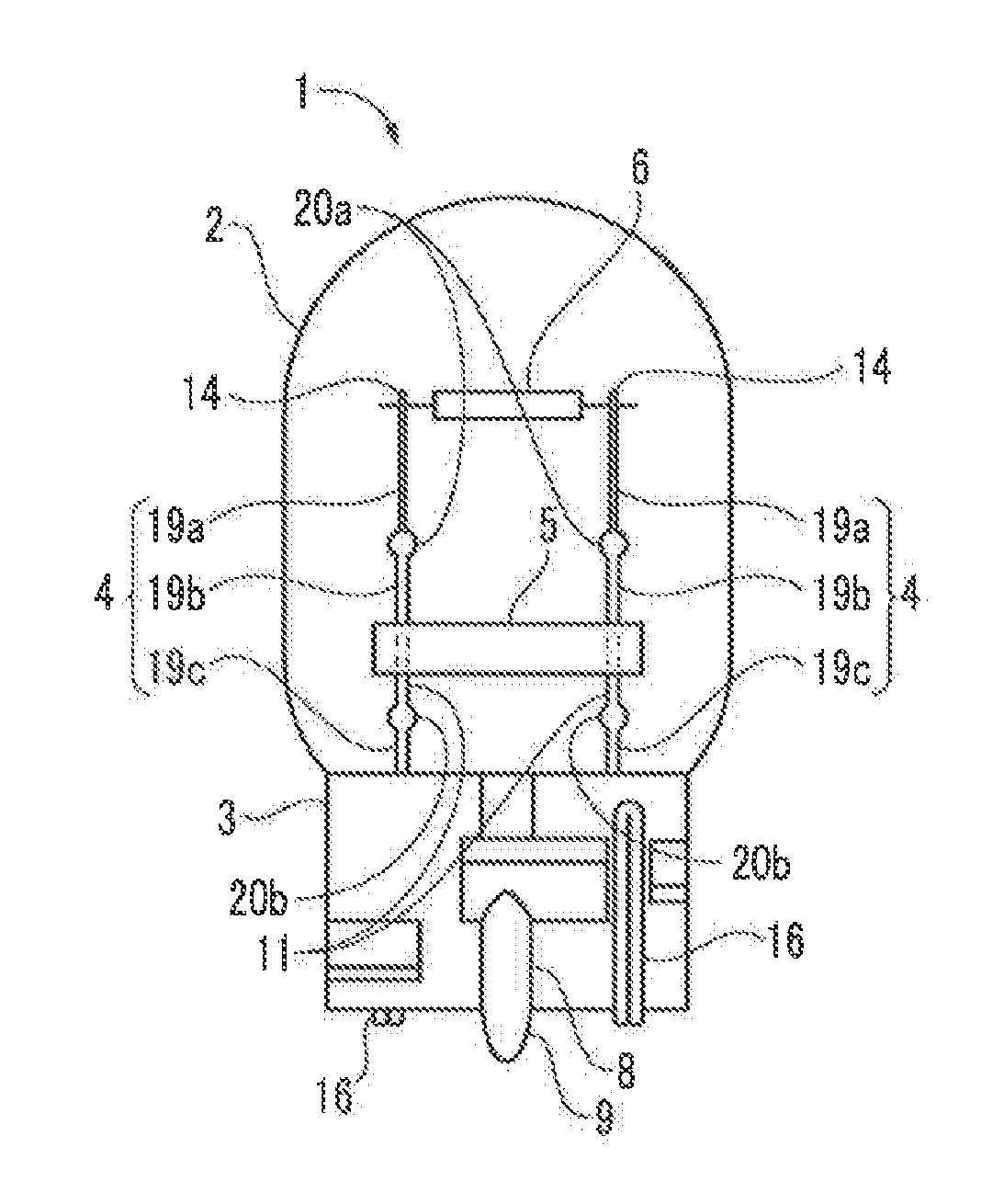
[0022]FIG. 1 is a side view of an incandescent lamp 1. The incandescent lamp 1 is provided as, for example, an automobile headlight at the front of the automobile.

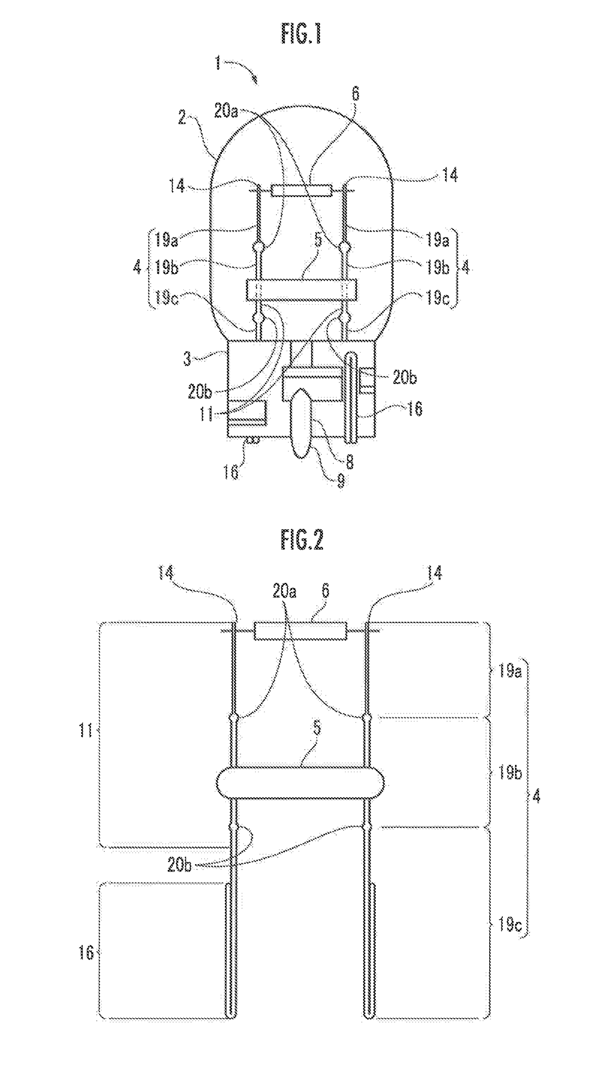
[0023]The incandescent lamp 1 includes a bulb 2, a pinch seal part 3, a pair of lead wires 4, a bridge 5, a filament 6, and an exhaust pipe 8. The bulb 2, the pinch seal part 3, the bridge 5, and the exhaust pipe 8 are formed of soft glass for the purpose of melting point reduction. In the present embodiment, the same glass material is used as the soft glass of the bulb 2, the pinch seal part 3, the bridge 5, and the exhaust pipe 8, which are all colorless and transparent. However, it is possible to appropriately adopt, for example, umber other than a solid color as a color of the bulb 2.

[0024]The exhaust pipe 8 is arranged on a side surface of the pinch seal part 3. While not yet subjected to pinch sealing processing in production processes of the incandescent lamp 1, the pinch seal part 3 is formed into a cylindrical sha...


PUM


Abstract

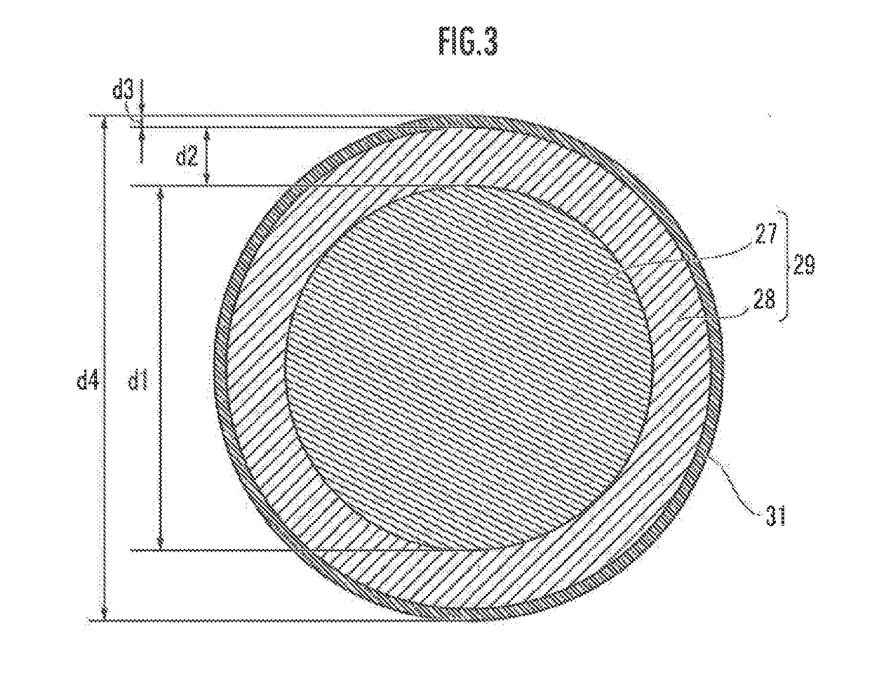
An incandescent lamp is provided which prevents disconnection of a coupling part between a filament and a lead wire and also which improves impact resistance. A lead wire 4 has, in a standing portion 11 inside of a bulb 2, a first zone 19a to a third zone 19c in order from a top. The third zone 19c further penetrates through a pinch seal part 3 while firmly fixed thereto. The first zone 19a and the second zone 19b are formed of materials consisting primarily of molybdenum and nickel, respectively. The third zone 19c is formed of a Dumet wire 29.

Description

BACKGROUND OF THE INVENTION[0001]Field of the Invention[0002]The present invention relates to an incandescent lamp loaded in, for example, an automobile.[0003]Description of the Related Art[0004]An incandescent lamp is known, as an automobile headlight, which includes: a bulb made of soft glass; a sealing part made of soft glass sealing the bulb; a pair of lead wires which has, in the bulb, standing portions standing from the sealing part in a manner such as to face each other and which penetrates through the sealing part while being firmly fixed thereto to be exposed to an outside of the sealing part; a filament which is arranged between the standing portions of the pair of lead wires and which has both end parts held at tip parts of the respective standing portions; and a bridge made of soft glass which is arranged between the standing portions of the pair of lead wires on a side located closer to the sealing part than the filament and which has both end parts coupled to the respe...

Claims


Application Information

Patent Timeline
IPC IPC(8): H01K1/40H01K1/38H01K1/28
CPCH01K1/40F21S48/1168H01K1/38H01K1/28H01J1/40F21S41/162H01K1/20H01K1/24H01K1/32
Inventor YASUDA, SATOSHI
Owner STANLEY ELECTRIC CO LTD
Why Eureka
Try Eureka