Hydraulic pump for a hydrodynamic compression tool

a technology of hydrodynamic compression and hydraulic pump, which is applied in the direction of manufacturing tools, portable power-driven tools, and positive displacement liquid engines, etc., can solve the problems of harmful to the operator and the tool, and achieve the effects of reducing the possibility of errors, protecting against possible damage, and saving tim

Inactive Publication Date: 2017-09-07
CEMBRE
View PDF12 Cites 14 Cited by
  • Summary
  • Abstract
  • Description
  • Claims
  • Application Information

AI Technical Summary

Benefits of technology

[0020]The pressure hose allows to access the part to be cut or compressed by means of the work head of the tool only, thus being able to operate in extremely small work spaces and position the pump housing at a distance such as not to interfere with the work space and to be protected against possible damage, e.g. due to explosions, sparks, flames in case of cutting and compressing of live electric cables or pipes of explosive or flammable materials.
[0021]The flexible control cable and the hand held remote control, provided with display and push-button panel, allow to select and visually check the selected operation mode near the work space and when the work head is positioned on the part to be either compressed or cut, without needing to move away from the work space to set the operation mode on the pump body and without needing to approach the entire pump body to the work space. Being able to perform the steps of positioning of the work head, select the pump operation mode and visually check the correspondence between the operation to be performed (cutting, compressing, opening the jaws and closing force adapted to the size and the material of the part) and the selected operation mode, in a single place and without movements of the pump body and of the operator, saves time and reduces the possibility of errors.

Problems solved by technology

Most compression and cutting operations, in particular those performed on electric cables, are hindered by very narrow space conditions or are performed in conditions (live electric conductors) which are potentially very dangerous for the operator and harmful for the tool.

Method used


Image

  • Hydraulic pump for a hydrodynamic compression tool
  • Hydraulic pump for a hydrodynamic compression tool
  • Hydraulic pump for a hydrodynamic compression tool

Examples


Embodiment Construction

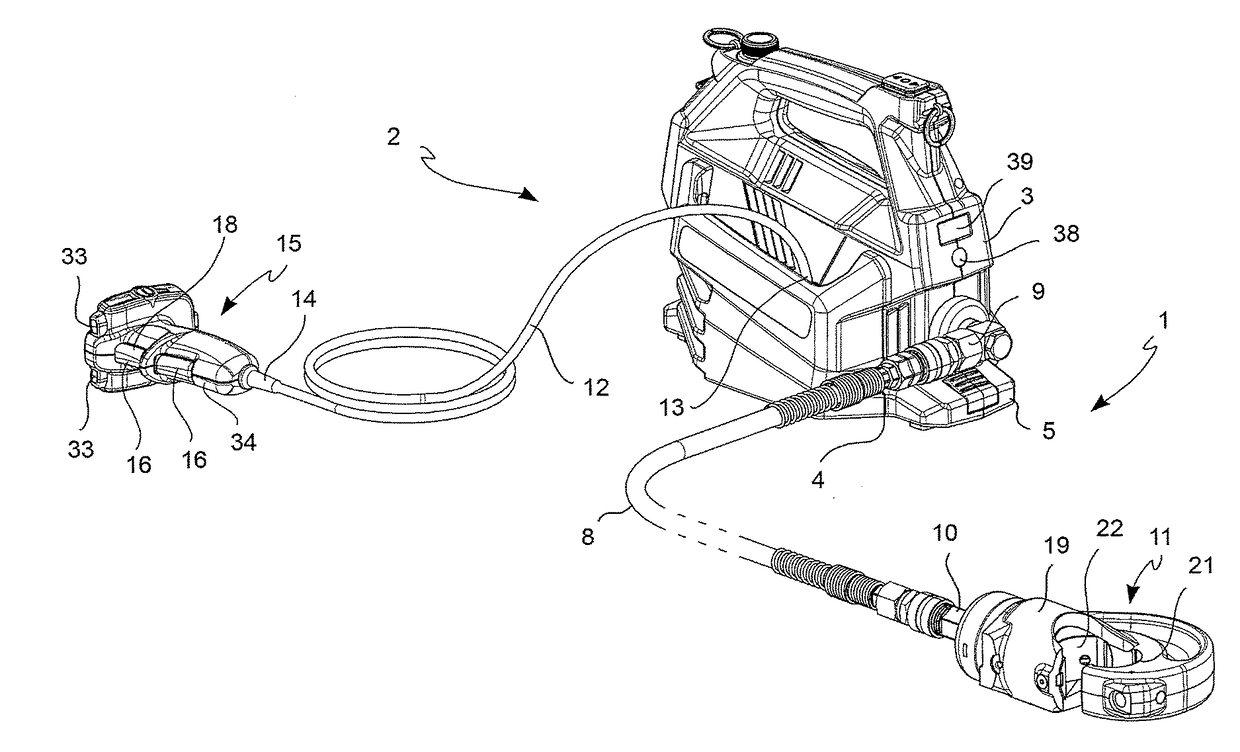
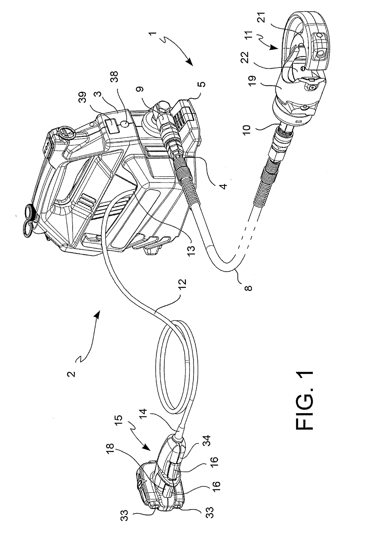
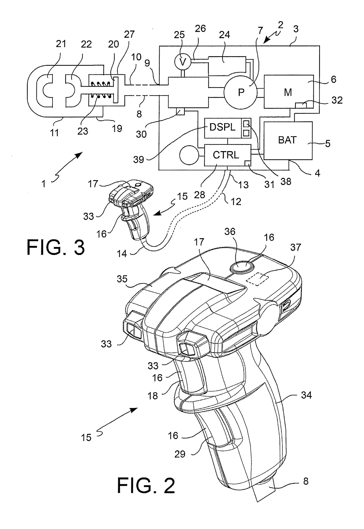
[0028]With reference to the figures, an electro-hydraulic pump 2 for hydrodynamic compression and / or cutting tools 1 comprises:[0029]a pump housing 3,[0030]an accumulator seat 4, adapted to receive the accumulator 5 and having electric terminals which make an electric contact with the accumulator 5,[0031]an electric motor 6, supported by the pump housing 3 which can be powered by the accumulator 5,[0032]a hydrodynamic group 7 (pumping group) supported by the pump housing 3 and connected to the electric motor 6 to increase the pressure of a hydraulic liquid in response to the movement of the electric motor 6,[0033]an electronic control circuit 28 connected to the electric motor 6 and with the accumulator 5 for controlling the electric motor 6,[0034]a flexible pressure hose 8 having a pump end 9 connected to the pump housing 3 and in communication with the hydrodynamic group 7, and an opposite work end 10 connectible to a work head 11 of the tool 1 which may be spaced apart from the p...


PUM

PropertyMeasurementUnit
period of timeaaaaaaaaaa
timeaaaaaaaaaa
timeaaaaaaaaaa

Abstract

An electro-hydraulic pump for hydrodynamic compression tools which comprises a pump housing carrying an electric motor and a hydrodynamic group for pressurizing a hydraulic liquid, a control circuit for controlling the electric motor, a flexible pressure hose connected to the hydrodynamic group, and a work head of the tool to communicate the hydraulic liquid pressure to the work head. A flexible control cable connects the control circuit in the pump housing to a hand held remote control. The hand held remote control comprises an actuating button for starting the electric motor and a button for selecting an operation mode of the electro-hydraulic pump from a plurality of pre-set operation modes, as well as a multifunction display which shows the selected operation mode.

Description

BACKGROUND OF THE INVENTION[0001]1. Field of the Invention[0002]The present invention relates to a hydraulic pump for a hydrodynamic compression and / or cutting tool and to a hydrodynamic compression and / or cutting tool.[0003]2. Description of the Related Art[0004]Hydrodynamic compression and / or cutting tools are often used to perform determined connection operations, e.g. for crimping connectors about electrical wires or hydraulic pipes and for compressing rivets, or for determined cutting operations, e.g. cutting electric wires during electric system installation and maintenance.[0005]Such tools comprise an electric motor and a hydraulic pump which causes an increase of a hydraulic liquid pressure operating on a piston to move the latter against the bias of a pressure spring. In turn, the piston is connected to a movable jaw so as to move the jaw, during the compression operation, with respect to a fixed jaw of the tool. The jaws may be shaped and / or provided with interchangeable a...

Claims


Application Information

Patent Timeline
Patent Type & Authority Applications(United States)
IPC IPC(8): B25B27/14F04B17/03F04B19/04F04B49/00H02K7/14F04B49/10F04B49/22B23D29/00H01R43/048F04B23/02F04B49/06
CPCB25B27/14F04B23/02F04B17/03F04B19/04F04B49/002H02K7/145F04B49/10F04B49/22B23D29/002H01R43/0486F04B49/065F04B49/06B25F5/005
Inventor BAREZZANI, GUALTIEROVEGLIANTI, SAMUEL
Owner CEMBRE
Why Eureka
Try Eureka