Cooling of a supply pipe in a hydrogen refueling system

a technology of hydrogen refueling and supply pipe, which is applied in the direction of hydrogen technologies, gas/liquid distribution and storage, vessel construction details, etc., can solve the problems of disadvantages such as the inability to meet the temperature requirement within a given period, the disadvantages of returning the hydrogen to the storage system, and the disadvantages of including the storage system in the return path of the hydrogen, so as to facilitate the cooling of the supply line and facilitate the temperature control of the supply lin

Active Publication Date: 2017-09-07
NEL HYDROGEN AS
View PDF15 Cites 23 Cited by
  • Summary
  • Abstract
  • Description
  • Claims
  • Application Information

AI Technical Summary

Benefits of technology

[0007]According to an embodiment of the invention the controller is configured for controlling the cooling system down to a temperature of minus 45° C. Being able to control the temperature of the cooling system and thereby the supply pipe in the range of e.g. minus 10° C. and minus 50° C. and the temperature of the hydrogen down to a temperature of e.g. minus 45° C. is advantage in that the net heat transfer between the cooling circuit (or refrigerant hereof) and the supply pipe (or the hydrogen hereof) can be reduced and preferably close to be eliminated.
[0040]According to an embodiment the controller facilitates cooling of the supply line at determined time intervals. The determined time interval could be a fixed value which ensures that the temperature of the hydrogen supply line does not exceed a given threshold value. Hence a time threshold could be said to be established which when exceeded initiates a flushing, which ensures a desired temperature of the hydrogen supply line.

Problems solved by technology

Accordingly, due to thermal inertia of components of the refueling system—e.g. the hydrogen feed line—it may be difficult to satisfy the temperature requirement within a given period from start of refueling.
Returning the hydrogen to the storage system may be disadvantageous due to the need for using lengths of pipes for returning the hydrogen back to the storage system.
Furthermore, including the storage system in the return path for the hydrogen may be disadvantageous due to possible additional cooling requirements.
Making the capacity of the cooling system dependent on the length between the compressor station and the dispenser are limiting the freedom of design of the hydrogen refueling station, which is not desirable.

Method used


Image

  • Cooling of a supply pipe in a hydrogen refueling system
  • Cooling of a supply pipe in a hydrogen refueling system
  • Cooling of a supply pipe in a hydrogen refueling system

Examples


Embodiment Construction

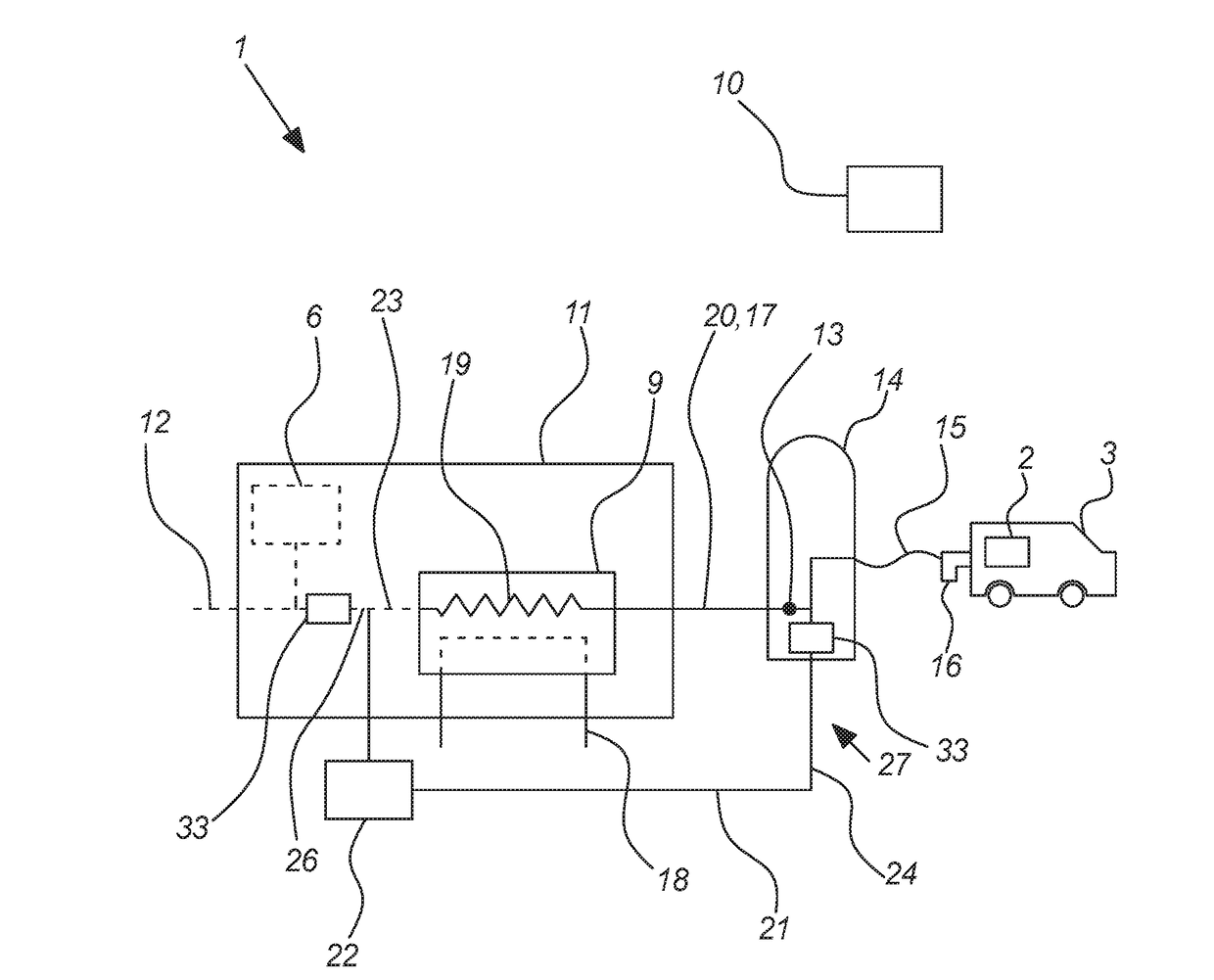
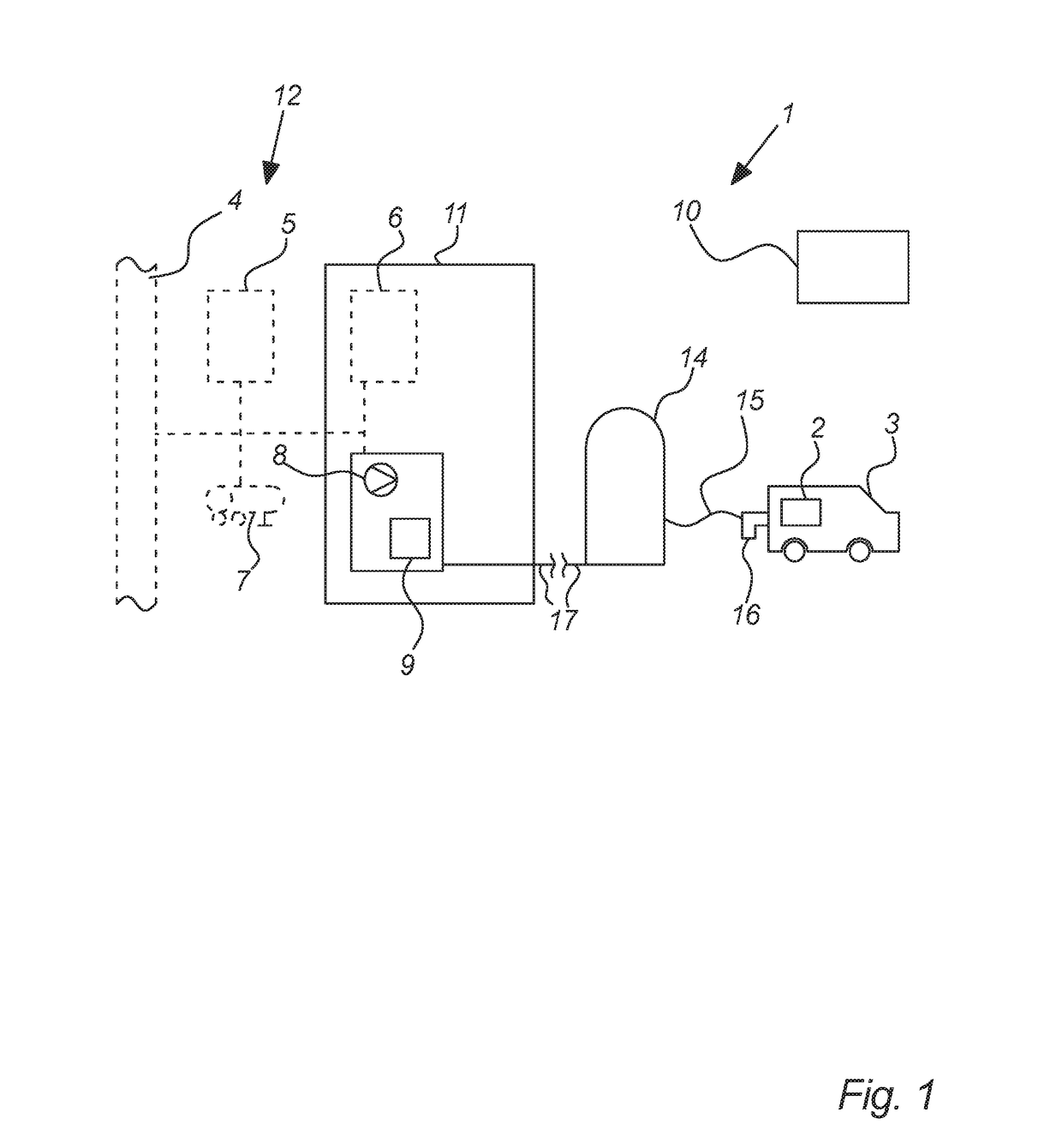
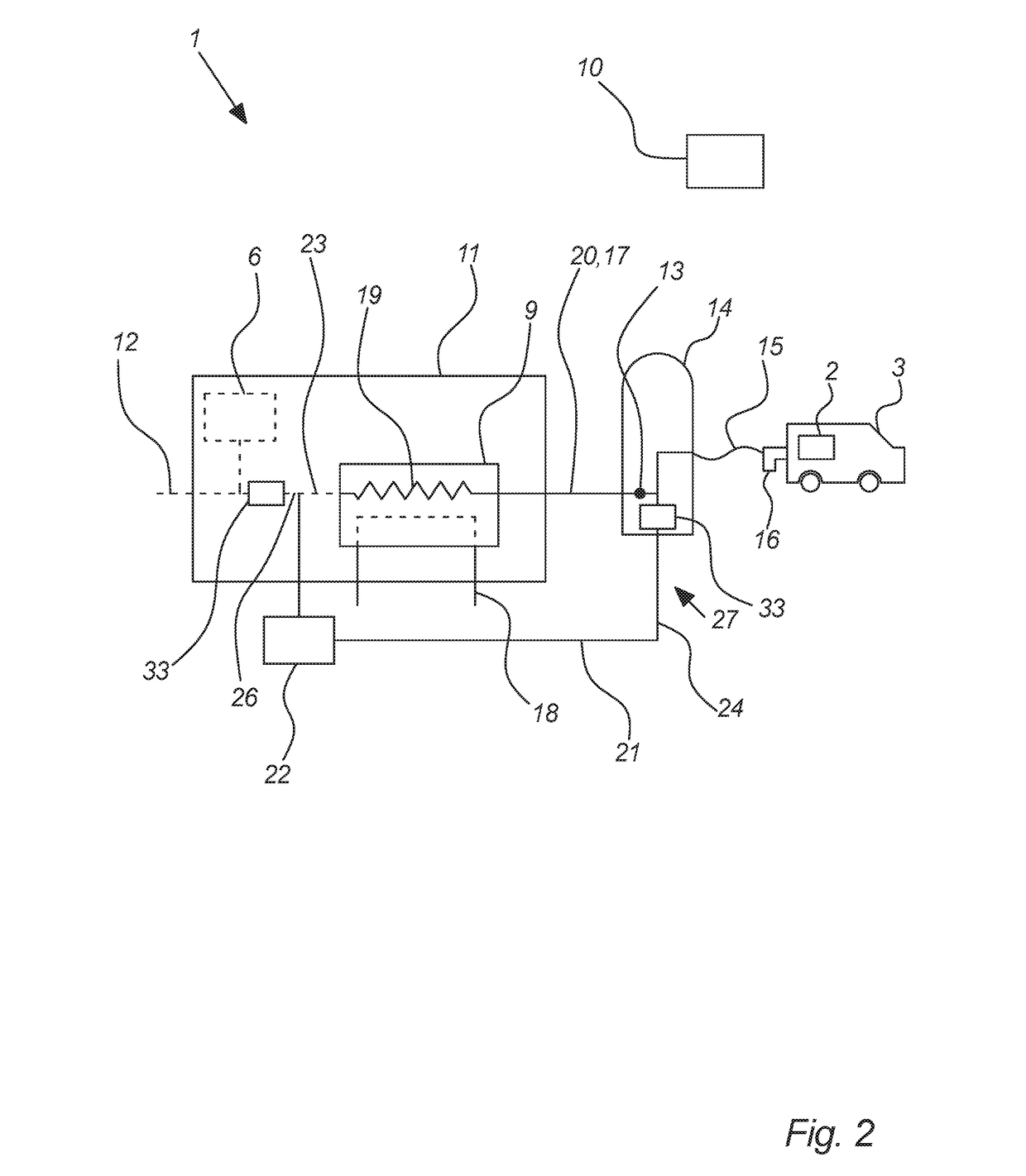
[0056]FIG. 1 illustrates a schematic view of a hydrogen refueling system 1 according to an embodiment of invention. The hydrogen refueling system 1 supplies hydrogen to a receiving vessel 2 of a vehicle 3 from a hydrogen supply 12 in the form of a supply network 4, external hydrogen storage 5, internal hydrogen storage 6 or a temporary hydrogen storage 7.

[0057]To regulate the hydrogen pressure, temperature, flow, time etc. to comply with currents standards such as e.g. the SAEJ 2601 standard for refuelling of a vehicle 3 with hydrogen, the hydrogen refueling system 1 comprises a compressor 8, a cooling system 9 and a control and monitoring system 10 all which are preferably located within the hydrogen center enclosure 11 of the hydrogen refueling system 1.

[0058]The cooling system 9 may be embodied by a heat exchanger. Further, since it is preferred that the cooling system 9 is located or partly located in the center enclosure 11, it should be understood that e.g. for practical reaso...


PUM


Abstract

a hydrogen refueling system for refueling a vehicle with hydrogen. The system comprises a hydrogen supply, a hydrogen center enclosure comprising a cooling system. The cooling system is arranged for cooling the hydrogen delivered to the vehicle. The system further comprises a dispenser arranged for supplying the hydrogen to the vessel of the vehicle. A supply pipe is arranged for guiding the hydrogen from the center enclosure to the dispenser. The system further comprises a forward path arranged for guiding a supply pipe cooling media from the hydrogen center enclosure towards the dispenser, and a return path arranged for guiding at least a fraction of the supply pipe cooling media back to the hydrogen center enclosure, where at least one of the forward and return paths are thermally connected with the cooling system.

Description

CROSS REFERENCES TO RELATED APPLICATIONS[0001]This application claims the benefit of Danish patent application No. PA 2016 00136 filed on 2 Mar. 2016, incorporated herein by reference.FIELD OF THE INVENTION[0002]The invention relates to hydrogen refueling systems, particularly to methods for cooling a supply pipe of such refueling systems.BACKGROUND OF THE INVENTION[0003]The temperature of the hydrogen supplied to a vehicle should preferably be within a range of minus 33° C. and minus 40° C. within a period of 30 seconds from start of the refueling. If e.g. during the night no refueling has been made to the hydrogen refueling station the hydrogen feed line may be heated to the ambient temperature which easily could be plus 5-10° C. Accordingly, when the first refueling is initiated after such period of no refueling, the cooling system has to cool the hydrogen to the desired temperature within the desired time from start of the refueling. Accordingly, due to thermal inertia of compon...

Claims


Application Information

Patent Timeline
Patent Type & Authority Applications(United States)
IPC IPC(8): F17C5/06
CPCF17C5/06F17C2221/012F17C2270/0581F17C2250/0439F17C2250/0631F17C2227/0353F17C5/00F17C2205/0332F17C2205/0355F17C2205/0364F17C2205/0376F17C2221/013F17C2227/0341F17C2227/0355F17C2250/03F17C2265/065F17C2270/0139Y02E60/32F17C5/04F17C13/025F17C13/026F17C13/028F17C13/04F17C2227/0135F17C2227/0358F17C2270/0178Y02P90/45
Inventor PETERSEN, LEIF KAPPELBOISEN, JESPER NISSEN
Owner NEL HYDROGEN AS
Why Eureka
Try Eureka