

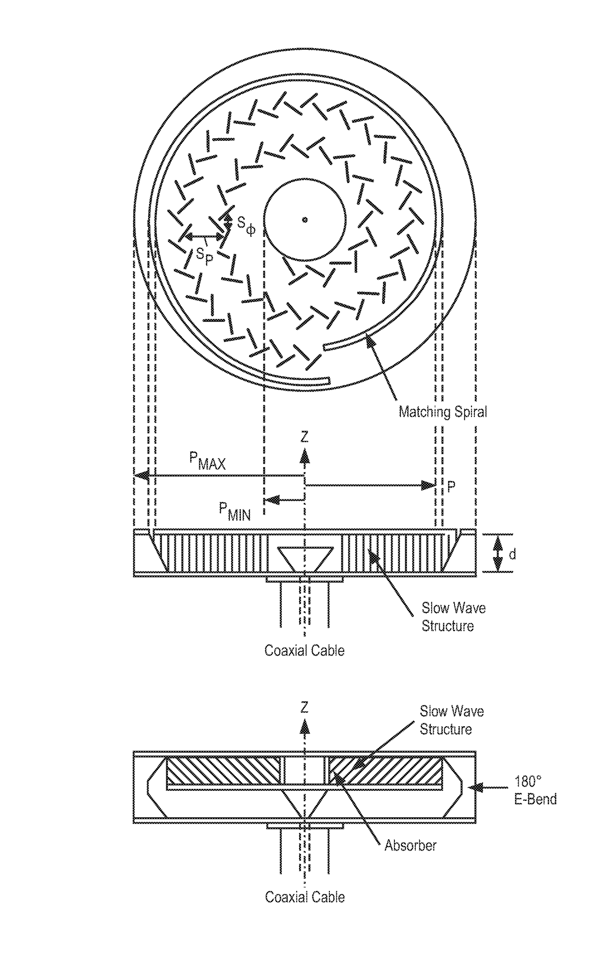
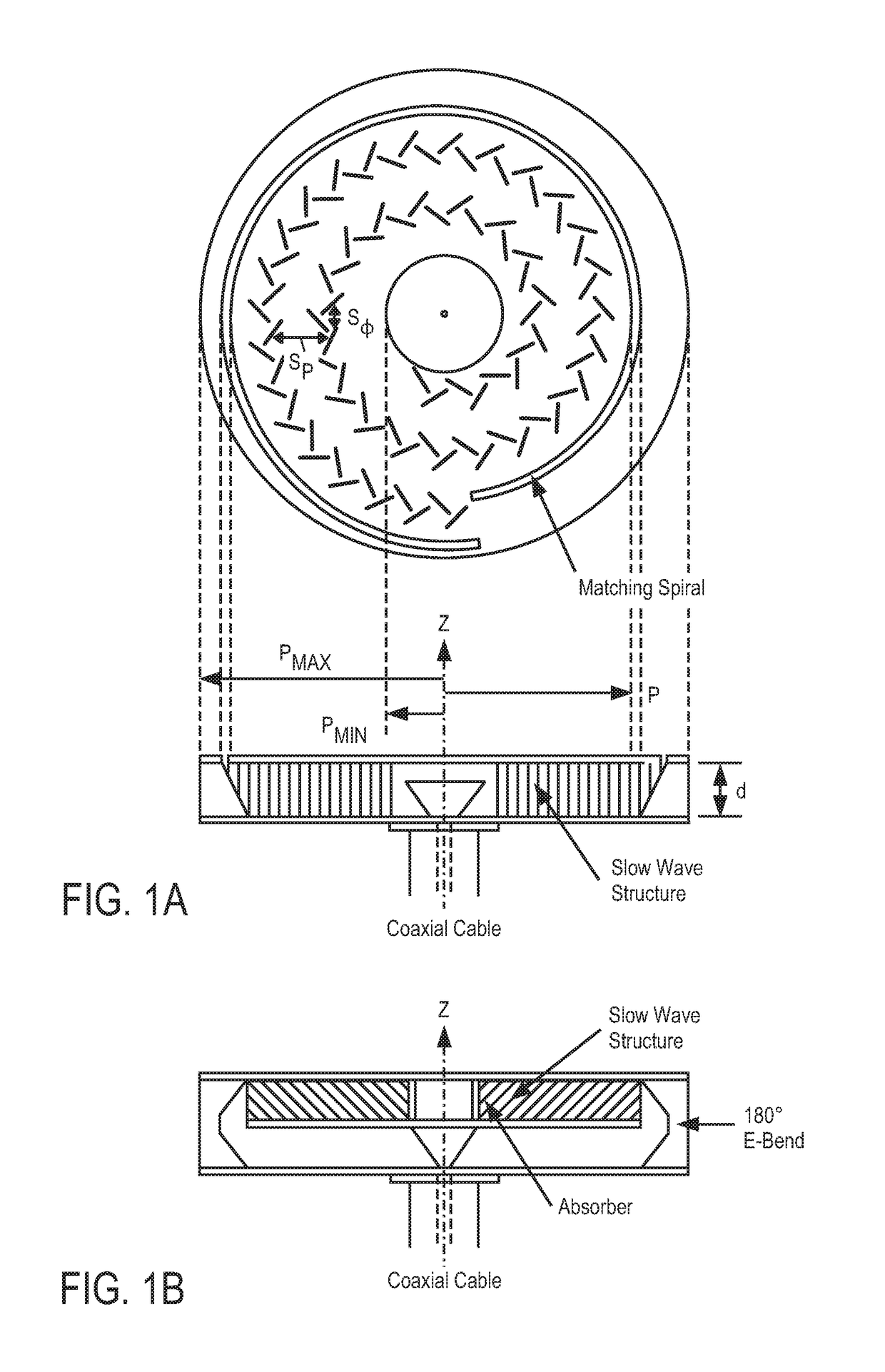
Broadband RF radial waveguide feed with integrated glass transition
a radial waveguide and integrated technology, applied in the field of antennas, can solve the problems of limited resonant of the launch structure, difficult to extend beyond 20% bandwidth, limit the average power handling capacity of the launch, etc. heat accumulated at the launch will be dissipated only through radiation
- Summary
- Abstract
- Description
- Claims
- Application Information
AI Technical Summary
Benefits of technology
Problems solved by technology
Method used
Image

Examples
example embodiments
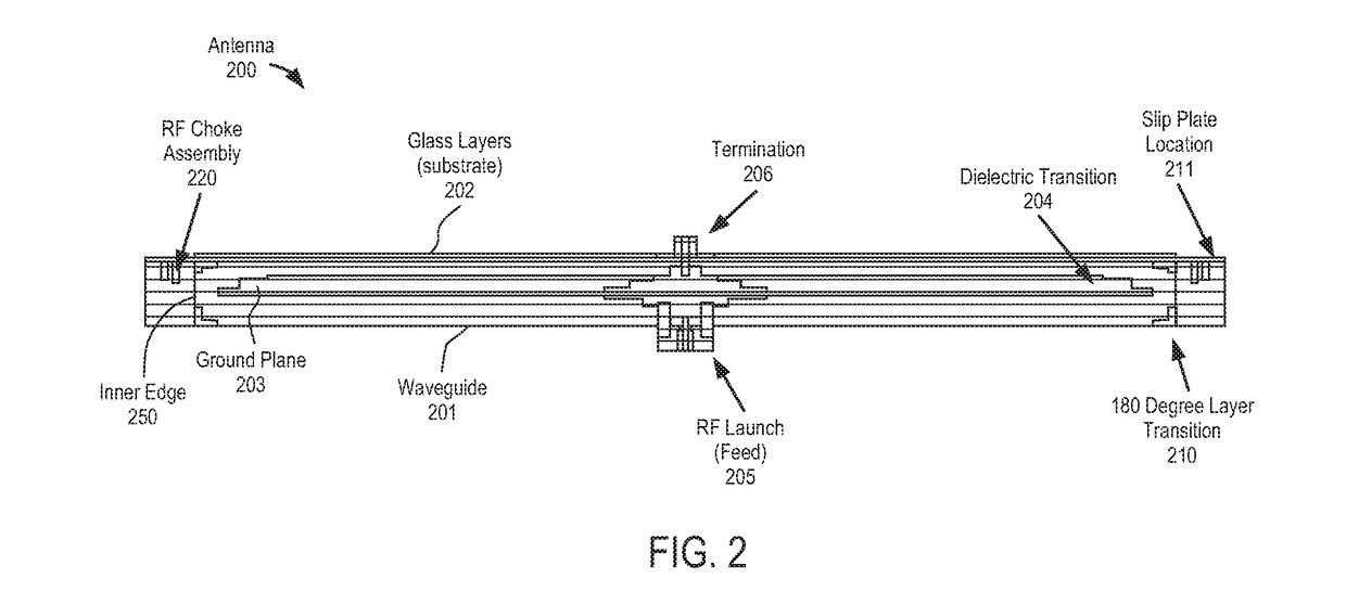
[0033]In one embodiment, an antenna is disclosed that comprises a radial waveguide; an aperture operable to radiate radio frequency (RF) signals in response to an RF feed wave fed by the radial waveguide; and a radio frequency (RF) choke operable to block RF energy from exiting through a gap between outer portions of the waveguide and the aperture. In one embodiment, there is no physical electrical connection between the waveguide and the aperture. In such a case, the two may be held in place with a clamp mechanism on the outsides of the waveguide and the aperture. Even so, there is no electrically conductive connection between the two. In one embodiment, a slip plane located in proximity to the gap and facilitates potential movement of the waveguide and / or the radiating aperture.
[0034]In one embodiment, the waveguide comprises metal and the aperture comprises a glass or liquid crystal display (LCD) substrate, and the coefficient of thermal expansion of the waveguide and the apertur...
examples of antenna embodiments
[0062]The techniques described above may be used with flat panel antennas. Embodiments of such flat panel antennas are disclosed. The flat panel antennas include one or more arrays of antenna elements on an antenna aperture. In one embodiment, the antenna elements comprise liquid crystal cells. In one embodiment, the flat panel antenna is a cylindrically fed antenna that includes matrix drive circuitry to uniquely address and drive each of the antenna elements that are not placed in rows and columns. Note that the feed need not be circular. In one embodiment, the elements are placed in rings.
[0063]In one embodiment, the antenna aperture having the one or more arrays of antenna elements is comprised of multiple segments coupled together. When coupled together, the combination of the segments form closed concentric rings of antenna elements. In one embodiment, the concentric rings are concentric with respect to the antenna feed.
Overview of an Example of Antenna Systems
[0064]In one emb...
an example system embodiment
[0121]In one embodiment, the combined antenna apertures are used in a television system that operates in conjunction with a set top box. For example, in the case of a dual reception antenna, satellite signals received by the antenna are provided to a set top box (e.g., a DirecTV receiver) of a television system. More specifically, the combined antenna operation is able to simultaneously receive RF signals at two different frequencies and / or polarizations. That is, one sub-array of elements is controlled to receive RF signals at one frequency and / or polarization, while another sub-array is controlled to receive signals at another, different frequency and / or polarization. These differences in frequency or polarization represent different channels being received by the television system. Similarly, the two antenna arrays can be controlled for two different beam positions to receive channels from two different locations (e.g., two different satellites) to simultaneously receive multiple...
PUM
 Abstract
Description
Claims
Application Information