Gate voltage control device

a gate voltage control and gate voltage technology, applied in the direction of process and machine control, instruments, pulse techniques, etc., can solve the problems of large size of isolation elements, difficult to directly connect them together, and large so as to reduce the size of gate voltage control devices

Active Publication Date: 2017-09-07
TOYOTA JIDOSHA KK
View PDF7 Cites 1 Cited by
  • Summary
  • Abstract
  • Description
  • Claims
  • Application Information

AI Technical Summary

Benefits of technology

[0007]In this gate voltage control device, the detection circuit detects the physical quantity and transmits the signal corresponding to the detected physical quantity to the primary circuit. If the reference voltage differs between the detection circuit and the primary circuit, an isolation element may be provided on a communication passage between the detection circuit and the primary circuit. The primary circuit applies the variable voltage that changes cyclically between both ends of each primary coil. In so doing, a variable voltage with a waveform corresponding to the variable voltage applied to the primary coil is generated in the corresponding secondary coil. Each of the secondary circuits converts the variable voltage generated in the secondary coil into the direct voltage. Each voltage regulator circuit is powered by the direct voltage converted by its corresponding secondary circuit as the power source. That is, a power supply circuit for supplying the direct voltage to the plurality of voltage regulator circuits is configured by the primary circuit, the plurality of isolation transformers, and the plurality of secondary circuits. Notably, the primary and secondary coils of each isolation transformer are isolated. Due to this, the primary circuit and the secondary circuit being a corresponding pair operate in different reference voltages. Further, in this gate voltage control device, the primary circuit receives the signal corresponding to the physical quantity detected by the detection circuit, and applies the variable voltage having the waveform type corresponding to this signal on the respective primary coils. Due to this, the variable voltages having the waveforms corresponding to the physical quantity are generated in the secondary coils as well. Each voltage regulator circuit changes the change-pattern of the gate voltage according to the waveform type of the variable voltage generated in its corresponding secondary coil. Thus, the voltage regulator circuit can change the change-pattern of the gate voltage according to the physical quantity. As described above, in this gate voltage control device, the signal indicating the physical quantity can be transmitted from the primary circuit to the respective voltage regulator circuits via the isolation transformers even if an isolation element is provided between the detection circuit and the primary circuit. The signal indicating the physical quantity can be transmitted to the respective voltage regulator circuits via the isolation transformers functioning as a part of the power supply circuit for supplying the direct voltage. Due to this, the isolation transformer dedicated to the signal transmission may not need to be provided for each voltage regulator circuit. Due to this, the insulation elements dedicated to the signal transmission can be omitted. Thus, according to this configuration, the size of the gate voltage control device can be reduced.

Problems solved by technology

A reference voltage may become large in the detection circuit and the voltage regulator circuit, and in this case, it is difficult to directly connect them together.
However, the isolation element has a large size due to its need to secure sufficient isolation performance.
Due to this, the gate voltage control device becomes large in size.

Method used


Image

  • Gate voltage control device
  • Gate voltage control device
  • Gate voltage control device

Examples


first embodiment

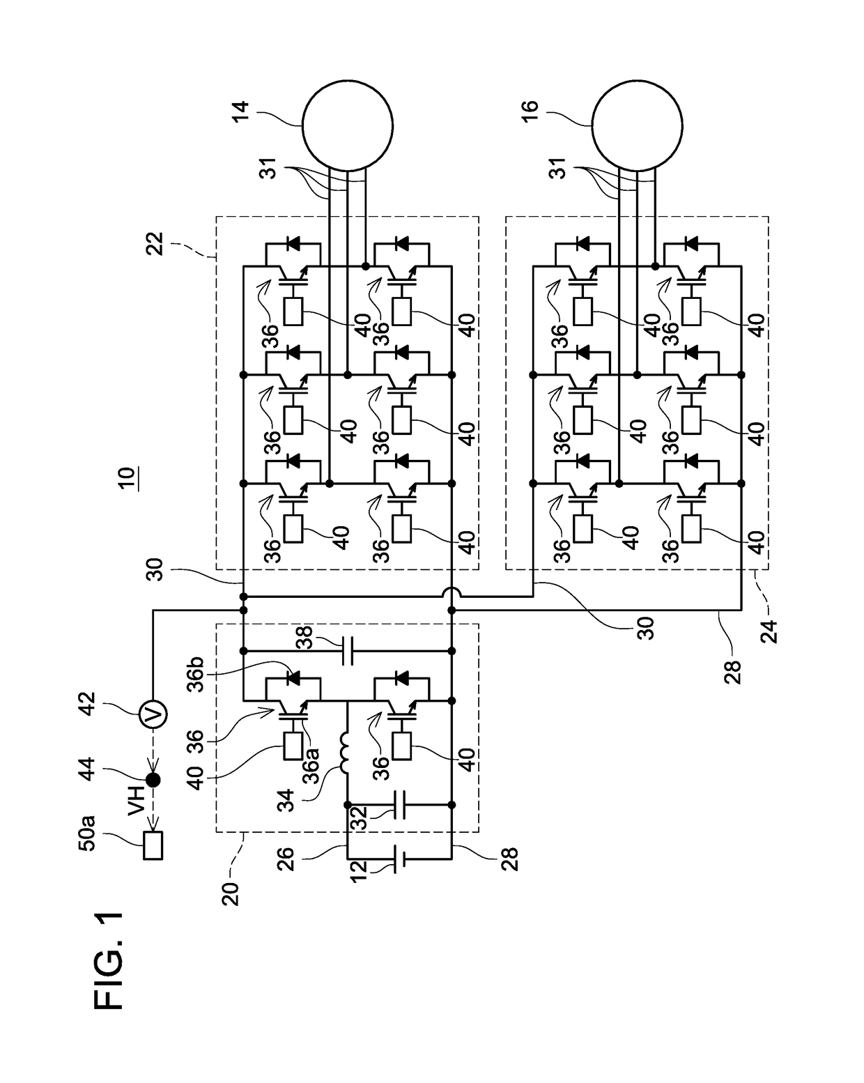
[0024]A motor driving circuit 10 shown in FIG. 1 converts a DC voltage from a battery 12 into a three-phase AC voltage and supplies the same to motors 14, 16. The motor driving circuit 10 includes a converter circuit 20, a first inverter circuit 22, and a second inverter circuit 24. The battery 12 and the converter circuit 20 are connected by a first high-potential wiring 26 and a low-potential wiring 28. The converter circuit 20 and the first inverter circuit 22 are connected by a second high-potential wiring 30 and the low-potential wiring 28. The converter circuit 20 and the second inverter circuit 24 are connected by the second high-potential wiring 30 and the low-potential wiring 28.

[0025]The converter circuit 20 includes a smoothing capacitor 32, a reactor 34, two RC-IGBTs (Reverse Conducting Insulated Gate Bipolar Transistors) 36, and a smoothing capacitor 38. The reactor 34 is provided on the first high-potential wiring 26. The smoothing capacitor 32 is connected between the...

second embodiment

[0056]A gate voltage control circuit of the second embodiment differs from the gate voltage control circuit of the first embodiment in the operation of the signal transmission control device 92b. Other configurations of the gate voltage control circuit of the second embodiment are same as those of the gate voltage control circuit of the first embodiment.

[0057]FIG. 5 shows an operation of the gate voltage control circuit of the second embodiment. The operation of the gate voltage control circuit of the second embodiment during the period T1 (when the potential VH is larger than the reference value) is same as that of the gate voltage control circuit 50 of the first embodiment. The operation of the gate voltage control circuit of the second embodiment during the period T2 (when the potential VH is equal to or less than the reference value) is different from that of the gate voltage control circuit 50 of the first embodiment.

[0058]In the second embodiment, the signal transmission contr...

third embodiment

[0062]In the gate voltage control circuits 50 of the first and second embodiments, there may be some cases where detection of the intermediate voltage by the detection circuit 71 becomes difficult due to the generation of ringing. The gate voltage control circuit of the third embodiment suppresses an influence of the ringing and ensures the detection of the intermediate voltage. Firstly, issues related to the ringing will be described.

[0063]In the gate voltage control circuit 50 of the first embodiment, if sufficient charges are stored in the smoothing capacitors 73b, the current IL1 flowing in the primary coils 80a and the current IL2 flowing in the secondary coils 80b become small as shown in FIG. 6. In this case, the current IL2 attenuates to zero in a midst of the off-period Toff. Then, the ringing is generated at the timing when the current IL2 had attenuated to zero, and the voltages VL1, VL2 greatly fluctuate. Due to this, the detection circuit 71 cannot detect the intermedia...


PUM


Abstract

A gate voltage control device includes a detection circuit, a plurality of isolation transformers including primary coils and secondary coils, a primary circuit connected to the primary coils, secondary circuits connected to the secondary coils, and voltage regulator circuits connected to the secondary circuits and gates. The detection circuit transmits signal corresponding to detected physical quantity to the primary circuit. The primary circuit cyclically performs applying a variable voltage in a waveform that corresponds to the signal transmitted from the detection circuit between both ends of each primary coil. Each secondary circuit converts the variable voltage generated in the corresponding secondary coil to a direct voltage. Each voltage regulator circuit is powered by the direct voltage converted by the corresponding secondary circuit as a power source, and changes a change-pattern of the corresponding gate voltage according to a waveform of the variable voltage generated in the corresponding secondary coil.

Description

CROSS-REFERENCE TO RELATED APPLICATION[0001]This application claims priority to Japanese Patent Application No. 2016-042656 filed an Mar. 4, 2016, the contents of which are hereby incorporated by reference into the present application.TECHNICAL FIELD[0002]The teachings disclosed herein relates to a gate voltage control device.BACKGROUND ART[0003]Japanese Patent Application Publication No. 2011-244521 discloses an inverter device in which a photocoupler is inserted in a signal transmission passage.SUMMARY[0004]A circuit that detects a physical quantity (for example, current or voltage of a main current circuit, a switching element temperature, instruction signals from outside, and the like) when the main current circuit is to be turned an or off by a switching element, and changes a change-pattern of a gate voltage of the switching element according to the detected value is being developed. In this type of gate voltage control device, a detection circuit that detects the physical qua...

Claims


Application Information

Patent Timeline
Patent Type & Authority Applications(United States)
IPC IPC(8): H02M1/088H02M3/335H02M7/5387
CPCH02M1/088H02M7/5387H02M2001/0054H02P27/06H02M3/33507H02P27/08H03K17/0828Y02B70/10H02M1/0054H02M1/08H02M3/28H03K17/0406H03K17/08
Inventor TOSHIYUKI, KENABO, SHOJI
Owner TOYOTA JIDOSHA KK
Why Eureka
Try Eureka