System and Method for Determining Structure of Material

a technology of material structure and sensing system, applied in the direction of resistance/reactance/impedence, material analysis, instruments, etc., can solve the problems of more determination and cluttering of reconstructed images, and achieve the effect of reducing errors and reducing errors

Active Publication Date: 2017-09-14
MITSUBISHI ELECTRIC RES LAB INC
View PDF2 Cites 8 Cited by
  • Summary
  • Abstract
  • Description
  • Claims
  • Application Information

AI Technical Summary

Benefits of technology

[0008]Accordingly, one embodiment of the invention discloses a method for determining an image of a distribution of permittivity of a material. The method includes propagating a pulse of wave through the material to receive a set of echoes resulted from scattering the pulse by different portions of the material; simulating a propagation of the pulse in the material using a neural network to determine a simulated set of echoes, wherein each node in a layer of the neural network corresponds to a portion of the material and assigned a value the permittivity of the portion of the material, such that the values of the nodes at locations of the portions form the image of the distribution of the permittivity of the material, and wherein connections between layers in the neural network models scattering events; and updating the values of the nodes by reducing an error between the received set of echoes and the simulated set of echoes to produce the image of the distribution of the permittivity of the material. At least some steps of the method are performed by a processor.
[0009]Another embodiment of the invention discloses a permittivity sensor for determining an image of a distribution of permittivity of a material, including at least one transceiver to propagate a pulse of wave through the material and to receive a set of echoes resulted from scattering the pulse by different portions of the material; and a processor to simulate a propagation of the pulse in the material using a neural network to determine a simulated set of echoes, wherein each node in a layer of the neural network corresponds to a portion of the material and assigned a value the permittivity of the portion of the material, such that the values of the nodes at locations of the portions form the image of the distribution of the permittivity of the material, and wherein connections between layers in the neural network models scattering events, and to update the values of the nodes reducing an error between the measured set of echoes and the simulated set of echoes to produce the image of the distribution of the permittivity of the material.
[0010]Yet another embodiment of the invention discloses a non-transitory computer readable storage medium embodied thereon a program executable by a processor for performing a method that includes requesting to propagate a pulse of wave through the material to receive a set of echoes resulted from scattering the pulse by different portions of the material; simulating a propagation of the pulse in the material using a neural network to determine a simulated set of echoes, wherein each node in a layer of the neural network corresponds to a portion of the material and assigned a value the permittivity of the portion of the material, such that the values of the nodes at locations of the portions form the image of the distribution of the permittivity of the material, and wherein connections between layers in the neural network models scattering events; and updating the values of the nodes reducing an error between the received set of echoes and the simulated set of echoes to produce the image of the distribution of the permittivity of the material.

Problems solved by technology

However, depending on the type of material, the received signal often resulted from the multiple reflections of the propagating pulse due to multiple scattering from the structures in the material, which results in artifacts that clutter the reconstructed image.
However, the multiple scattering of the pulse affects the pulse in a non-linear manner, making such a determination more difficult.

Method used


Image

  • System and Method for Determining Structure of Material
  • System and Method for Determining Structure of Material
  • System and Method for Determining Structure of Material

Examples


Embodiment Construction

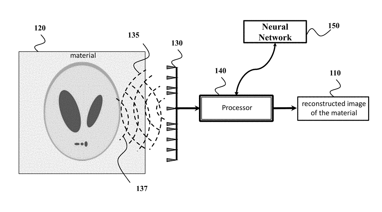
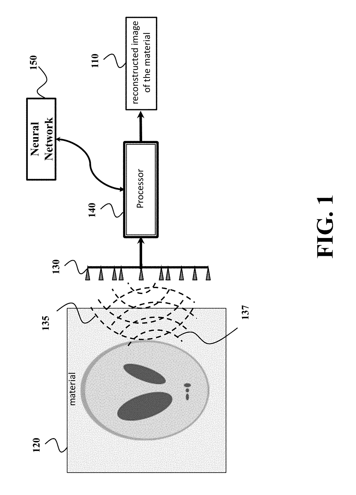
[0020]FIG. 1 shows a block diagram of a permittivity sensor for determining an image 110 of a distribution of permittivity of a material 120 according to one embodiment of the invention. The permittivity sensor includes at least one transceiver 130 to propagate a pulse of wave 135 through the material 120 and to receive a set of echoes 137 resulted from scattering the pulse by different portions of the material.

[0021]For example, the transceiver can include at least one transmitter that transmits the pulse through the material, such that the pulse scattered by the material produces the set of echoes 137. The pulse can be any type of electromagnetic or optical waves, such as one or combination of a microwave pulse, a radar pulse, a laser pulse, an ultrasound pulse, an acoustic pulse. The transceiver can also include at least one receiver arranged at a predetermined location with respect to the transmitter for receiving the set of echoes 137. According to different embodiments, the pe...


PUM

PropertyMeasurementUnit
permittivityaaaaaaaaaa
weightsaaaaaaaaaa
dielectric permittivityaaaaaaaaaa

Abstract

A method propagates a pulse of wave through the material to receive a set of echoes resulted from scattering the pulse by different portions of the material and simulates a propagation of the pulse in the material using a neural network to determine a simulated set of echoes. Each node in a layer of the neural network corresponds to a portion of the material and assigned a value the permittivity of the portion of the material, such that the values of the nodes at locations of the portions form the image of the distribution of the permittivity of the material. The connection between two layers in the neural network models a scattering event. The method updates the values of the nodes by reducing an error between the received set of echoes and the simulated set of echoes to produce an image of the distribution of the permittivity of the material.

Description

FIELD OF THE INVENTION[0001]This invention relates to sensing systems and methods, and more specifically to system and method for determining an image of a distribution of permittivity of a material.BACKGROUND OF THE INVENTION[0002]Knowledge of the spatial distribution of the dielectric permittivity within a material is important for many applications such as microwave imaging, biomicroscopy, medical imaging, through-the-wall imaging (TWI), infrastructure monitoring, and seismic imaging. In particular, determination of permittivity enables the visualization of the internal structure of the material and characterization of its physical properties. For example, in microwave imaging permittivity provides the structure and properties of objects in the material. In biomicroscopy, the permittivity allows to visualize the internal cell structure in three-dimensions. In TWI, the permittivity allows to learn the dielectric properties of the wall and to use that information to compensate for ...

Claims


Application Information

Patent Timeline
Patent Type & Authority Applications(United States)
IPC IPC(8): G01R27/26G06N3/04G06N3/08G01N22/00
CPCG01R27/2623G06N3/08G06N3/04G01N22/00G06N3/084
Inventor KAMILOV, ULUGBEKLIU, DEHONGMANSOUR, HASSANBOUFOUNOS, PETROS T.
Owner MITSUBISHI ELECTRIC RES LAB INC
Why Eureka
Try Eureka